Original EFDC Sediment Model
- Former user (Deleted)
- Kester Scandrett
- Former user (Deleted)
- Former user (Deleted)
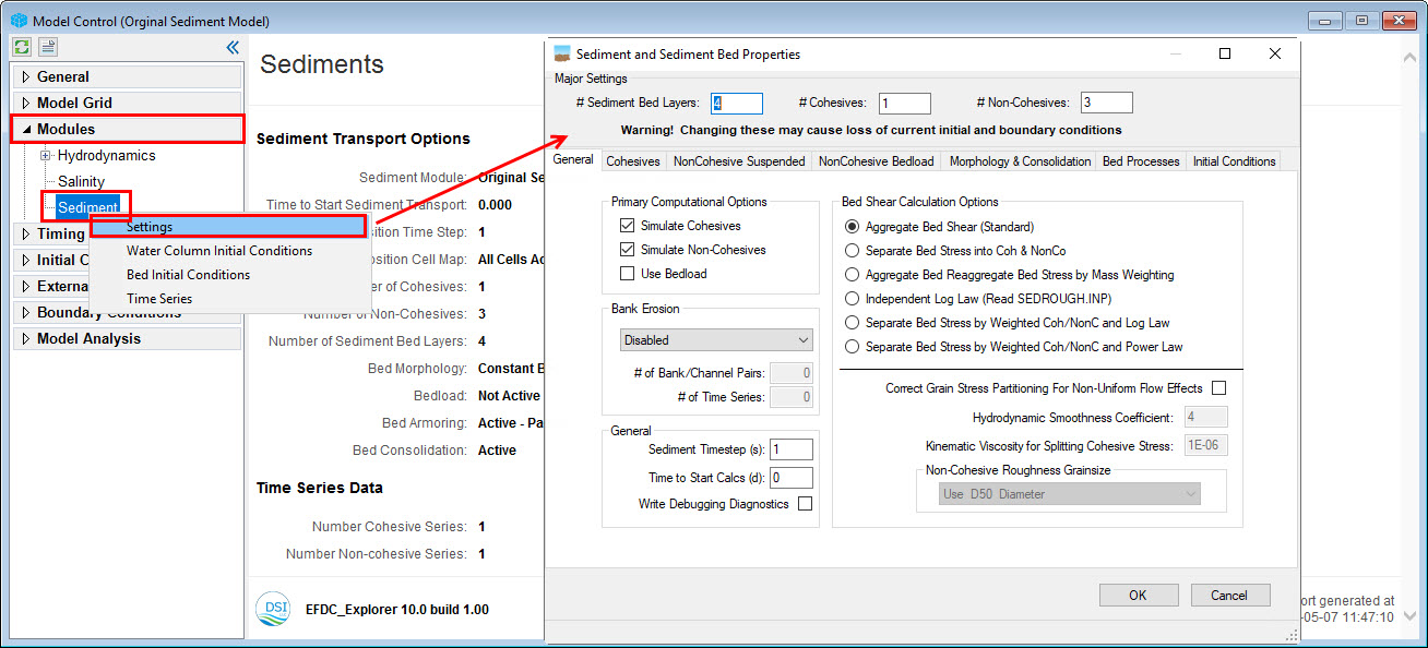
The sediment transport parameters and options are set by RMC on Sediment under Modules menu, then LMC on Settings (Figure 1). The Sediment and Sediment Bed Properties form has a number of tabs for configuring the sediment model. These include: General, Cohesives, Non-Cohesive Sediment, NonCohesive Bedload, Morphology and Consolidation, Bed Processes, and Initial Conditions. Each of these tabs are described below in separate sections. The user also has further options for setting the sediment bed with EE's Sediment Bed Initialization Tools.

General Tab
The principal settings for the number of sediment classes and bed layers are specified in the top frame under Major Settings (1) as shown in Figure 2. The user should define the number of sediment bed layers, cohesive and non-cohesive sediments. However, as with the toxics, these Major Settings parameters should only be changed with care and usually early in the model calibration process so as not to lose your initial and boundary conditions.
In the General tab, the user can tell EFDC whether or not to simulate cohesives and/or non-cohesives and the approach to compute bed shear stresses for sediment transport. Unchecking the Simulate Cohesives and/or Simulate Non-Cohesives check box does not delete previously defined sediment transport parameters, it just turns off the EFDC computations for that parameter.
The Sediment Timestep is a multiple of the number of hydrodynamic time steps to calculate between each sediment bed process computation (i.e. deposition, erosion, consolidation, etc.). Because the bed processes are slow, relative to the hydrodynamics, this number can often be 10 or greater. The user should conduct testing by starting with a low number and increase the Sediment Timestep until the user detects a noticeable difference in the model results. Then the number should be reduced by some amount in order to provide a safety factor. This can then be used for the subsequent calibration and production runs.
The Bed Shear Calculation Options allows the user to choose from a number of different calculation options for bed shear stress computations. If non-cohesive and cohesive calculations are being performed, it is generally preferred to use the Separate Bed Stress into Coh & NonCo option.
Figure 2. Sediment Transport – General.
Cohesive Sediments Tab
Figure 3 shows an example of the Cohesives tab in the Sediment Transport form. The user should specify the Cohesive Settling Flag where: 0-Simple; 1-Huang and Metha; 2-Shresta and Orlob; 3-Ziegler and Nesbit; 98-Lick Flocculation; 99-Lick Flocculation with Advective. If the Apply Vertical Diffusion check box is selected then vertical diffusion will be applied to the cohesives. When the Use Bulk (Mass) Erosion check box is selected the bulk erosion critical stress and rate will be used in the functions CSEDTAUB and CEDRESSB (still experimental at this time).
The number of columns shown in the input parameter grid varies with the number of classes to be modeled. The Diameter setting located at the bottom of the parameter grid sets the grain size that will be used in calculating d50's for the sediment bed. It is not used for any other calculations.
Maximum and minimum Cohesives Fluid Concentrations may be set by the user. Checking the Use Fluid Mud checkbox will include cohesive fluid mud viscous effects using function CDEVIS (SEDT).
For many of the fields in the Erosion & Deposition Parameters grid, clicking on a cell and pressing F2 pops up helpful information for that field.
Figure 3. Sediment Transport – Cohesives.
Non-Cohesive Sediments - Suspended Tab
Figure 4 shows the form with the Non-Cohesives Suspended tab. It is similar in function and operation to the Cohesives tab. Grain size for each non-cohesive class is required for the sediment transport computations. This value is also used as the grain size for the d50 calculations. A number of options for computing equilibrium concentrations are available in the Equilibrium Conc frame. This includes the option of equilibrium concentrations calculated from Sedflume data with or without critical shear stress. Setting the settling velocity or the critical shear stress values to numbers <0 results in EFDC computing those parameters values using the Van Rijn equations (1984a, 1984b). Pressing F2 for help pops up information relevant to the current input field.
The Sediment Info button provides a sediment properties calculator which uses the Van Rijn equations to compute the critical stress and setting parameters. Pressing the Set Parameters button will initialize the sediment properties using the Van Rijn equations if the sediment diameter is specified prior to pressing the button.
Figure 4. Sediment Transport – Non-Cohesives Suspended.
Non-Cohesive Sediments - Bedload Tab
Figure 5 shows the tab for the Non-Cohesives Bedload. The use of the Gamma parameters varies slightly between the different EFDC codes. The user should know how the Gamma's are used by reviewing the code prior to finalizing the desired inputs.
Pressing the Initialize Constants button will bring up a dialog box asking the user to select the bedload approach to use. EFDC+ Explorer sets the bed load transport constants to standard literature values for the computational approach selected.
The Bedload Phi Options frame allows the user to choose from the following options Constant/Manual, Van Rijn, Engelund-Hansen, and Wu, Wang & Jia.
The Cell Face Transport Rate Option allows calculation based on the following options: Downwind Projection; Downwind Projection with Corner Correction; and by Averaging Vector Components. The Maximum Allowable Adverse Slope for Bedload setting will prevent bedload movement if cell to cell slope is > BLBSNT when BLBSNT is > 0.
Figure 5. Sediment Transport – Non-Cohesives Bedload.
Morphology and Consolidation Tab
Figure 6 shows the tab for the Morphology & Consolidation of the sediment properties option. In this tab the user may specify various bed consolidation and bed morphology settings.
The Bed Morphology Options form allows the user to choose between use morphologic feedback to hydrodynamics or not (uncheck or check on checkbox). And Bed & Depositions Settings frame allows user sets bed change parameters
Class Maximum Grain Size frame statistics the maximum grain size of each sediment layer.
Bed Consolidation & Mechanics Options frame provides input to the main sediment bed consolidation options. The Bed Mechanics option must be 0-None, 1-Simple, or 2-Finite Strain. Option 2 is very a specialized approach and requires a detailed understanding of the of the Finite Strain implementation in the FORTRAN code. The consolidation rate is in seconds, not 1/seconds as earlier versions of EFDC.INP reported. The rate will usually be >100,000 seconds. The impact of the rate of consolidation can easily be tested using EFDC+ Explorer's Single Column Sediment Layers post-processing function (see Sediment Bed Process Tools).
Figure 6. Sediment Transport – Morphology and Consolidation.
Bed Processes Tab
The options for the bed processes tab are shown in Figure 7. EFDC+ Explorer employs an optional bed armoring functionality, allowing the user to select from: No Armoring; Non-Cohesive Armoring for Garcia-Parker; and Armoring with Active Parent Layering. The layer options frame is displayed based on which armoring option is selected. For the case of armoring with Active-Parent layering, the user needs to specify an active layer thickness, usually <5 cm but based on the d50's, and whether the active layer is controlled by mass or thickness. EFDC can optionally initialize the active layer using the initial condition bed layering. This is a good approach for initial setup of a model when the bed configuration is not well defined.
The user may also specify the Non-Cohesive Resuspension Options, with a choice of modifications based on coefficients input by the user. This option modifies the critical shear stress for resuspension (i.e TAUR) based on the fraction of cohesives.
In Hard Bottom Option frame, user can define which bed processes are active or not for a region or all grid cells. When user checks on Use Cell by Cell Hard Bottom Assignment using BEDMAP.INP checkbox, the Assign button will enable the user to configure the cells by assigning a value of 0 for a hard bottom and 1 for cells with active bed processes. When a cell is set as having a hard bottom it means that sediment won't erode or settle on these cells, they and will stay in layer one of the water column.
Figure 7. Sediment Transport – Bed Processes.
Initial Conditions - Sediments Tab
Figure 8 shows the sediment parameters form with the Initial Conditions tab selected. On this form the user selects how they would like to initialize the bed sediments for the model. This is done by selecting the option from the Sediment Initial Conditions Options frame. These options include: Constant Water Column and Bed; Spatially Varying Water Column; Spatially Varying Bed Conditions; and Spatially Varying Bed and Water Column.
If the user selects Bed Mass Specification Options to specify the mass fraction, then and the BEDLAY.INP will required as an additional IC file.
Figure 8. Sediment Transport – Initial Conditions.
Click on the Assign Bed IC button to open Initialization of Sediment Beds frame. The Initialization of Sediment Beds frame provides a number of options to build sediments beds which are described in more detail in the Sediment Bed Construction section.