Boundary Groups Tab
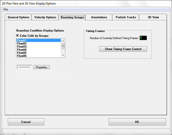
The way boundary conditions are displayed may specified by the user as shown in Figure 1. The boundary conditions are listed in the Boundary Condition Display form. The Color Cells by Groups check box will allow all boundary conditions of a similar type to be of the same color.
Figure 1 ViewPlan Display Options: Boundary Conditions.
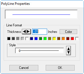
Clicking on one of the boundary conditions followed by the Properties button allows the user to select the polyline properties such as color, like thickness and line style as shown in Figure 2.
Figure 2 Typical Polyline Properties Options.
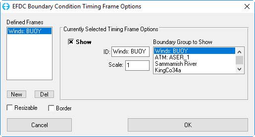
The Timing Frames frame provides the user with the number of currently defined timing frames that are displayed for each boundary condition on the ViewPlan. To edit this select the Show Timing Frame Control button. The form shown in Figure 3 allows the user to define new frames by selecting the New button. Each defined frame corresponds to boundary condition listing in the Boundary Group to Show frame with the selected BC highlighted in blue. The scale of the timing frame may be adjusted up or down to set the Y-axis to most suitable level.
The value of the scale field is dependent on what type of boundary forcing time series is selected. For winds the scale is m/s, for flows and pressure the scale is days. RMC on the Timing Frame allows the user to jump to the time selected on the frame.
Figure 3 Timing Frame Options Control.


