Generating a New Model
- Kester Scandrett
- Duy Pham
- Former user (Deleted)
After opening EE10, there are a number of different ways to create a new model. These all start with the grid utility, and there are three different ways to open it:
- The first way is to click Model button on the main menu toolbar, then select New Model (see Figure 1).
- The second way is to click New Model button directly on the main menu toolbar (see Figure 2).
- The third way is to press Ctrl+N.

Figure 1. Creating a New Model (1).

Figure 2. Creating a New Model (2).
After one of these three methods is selected, the Grid Generator form appears. There are four Grid Options on the Grid Generator form. These include Generate Uniform Grid, Generate Radial Grid, Generate Telescoping Grid, and Import Grid from Files. Each of these options is described below:
Generate Uniform Grid
This option allows users to generate a Cartesian grid. When the radial button for this option is selected, the Uniform Grid Options frame is shown. In this frame, the user needs to enter the Lower-Left and Upper-Right coordinates, these two corner points will temporarily limit the grid domain. Next, enter cell size in X and Y directions, which will define cell dimensions (width and length in meters of a cell), then click the calculator symbol for Number of Cells, the number of cells will be updated instantly. Another option is that the user enters the number of cells desired first, then click the calculator symbol for Cell Size and the dimensions of the cell will be updated.
Rotation Angle: The user should enter an angle in degrees which for the grid should be rotated.
UTM Zone: This is the Universal Transverse Mercator (UTM) zone, the user can enter the zone number, from 1 to 60.
The user can then click the Generate button, and the grid will appear on the right window, as shown in Figure 3. In case the user wants to save the information entered into the Uniform Grid Options frame this can be done by clicking the Save Parameters button, a Save As form will be displayed in order to allow the user to enter a file name and then click the Save button to save, as shown in Figure 4. This parameter settings file can be reused at another time by clicking on the Load Param button.

Figure 3. Generate Uniform Grid.
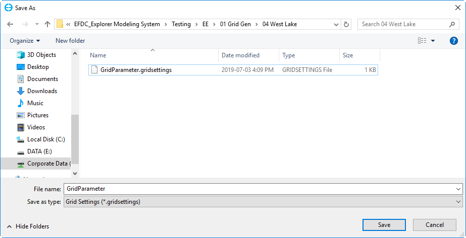
Figure 4. Save parameters.
If the user wants to restrict the domain size, they can use a bounding polygon, which is considered a shoreline. RMC on the Bounding Polygons text box and select Add Files. The Open form appears, and the user should select the file or files needs then click Open button as shown in Figure 5.
The polygon will be loaded, and the Lower-Left, Upper-Right coordinates will be updated, and the user can now generate a grid which is based on either cell size or number of cells by clicking on Generate button. It is also possible to inverse the selection or remove the cells that are outside of the bounding polygon by clicking the Remove Dry button as shown in Figure 6. The grid is generated with cells outside of the bounding polygon removed, is shown in Figure 7 in the 2DH View.

Figure 5. Load bounding polygon file.

Figure 6. Grid generation by using a bounding polygon.

Figure 7. Grid generated using bounding polygon.
When the grid is generated, the user can save it by clicking the Export Grid button. The grid can be exported as *.gpc; *.CVL or *.GRD format. Click the OK button to finish generating the uniform grid.
Generate Radial Grid
This option allows the user to generate a radial grid as seeing Figure 8.

Figure 8. Generate Radial Grid.
Generate Telescoping Grid
This option allows the users to generate a telescoping grid, as shown in Figure 9.

Figure 9. Generate Telescoping Grid.
Import Grid from Files
This option allows users to import an existing grid file. Grid file formats that are supported include:
- Grid+
- RGFGrid
- Grid95
- DXDY/LYLY
- ECOMSED
- SEAGRID
- CH3D
- Corners (4)
Select the option Import Grid from Files, and then click the Set button to set a projection of the grid, as shown in Figure 10. In case there are a number of sub-grids for a waterbody, the Use the same projection for all imported grids option needs to be checked.
After clicking the Set button, a Coordinate System form will appear as shown in Figure 11. Select a proper projection and then click the OK button. Then, this form will be closed.
Back to the form of Figure 10, the Import Grids is enabled, click on it. The Import Grid form will pop up, as shown in Figure 12. The user selects a grid type and browses to the grid file folder. Select the grid file, then click the OK button. In case of importing multiple grid files, the checkbox Multiple Grid Files needs to be checked before clicking the Browse button. To select multiple grid files at the same time, hold the Ctrl key and select the grid files, then click the OK button to load the grid files (see Figure 13).

Figure 10. Import from a grid file.

Figure 11. Set Coordinate System form.

Figure 12. Import Grid form.

Figure 13. Imported Grid preview.