The form for setting the hydraulic control structure boundary condition is shown in Hydraulic Structures Boundary Condition Editor – Flow Derived. The hydraulic structure boundary condition uses a head lookup table to describe the relationship between head and flow for that cell and is set with the Flow Control Type menu. Several options are available for the flow control type including:
- Flow derived from Upstream Depth
- Flow derived from Elevation Difference
- Flow derived from Elevation Difference with Flow Accelerations
- Flow derived from Upstream and Downstream Elevations
- Flow derived from Upstream Depth with Low Chord
- Flow derived from Elevation Difference with Low Chord
Using the flow acceleration parameter flows are now squared and multiplied by an acceleration factor when passing through an inlet.
Figure 1 Hydraulic Structure Boundary Conditions: Low Chord Option.
With Cell Options, the Rating Table/Flow Lookup Table frame allows the user to set the head for each table. After the user has selected the table number, the All button applies the current flow table setting for cells in the current group. The user may also enter an Offset which will apply an offset to the result of HP + BELV to obtain the H to look up from the H vs Q table.
The Shift All button prompts the user for an offset, after which a uniform shift is applied to all the offsets in the group.
The rating curve may also be generated within the Generate Rating Curve from a Power Series frame.
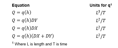
The user sets the hydraulic structure options in the Boundary Condition Group frame. The dropdown menu allows selection from the following equations for the boundary flow multiplier, where q(h) are unit discharges and need to be multiplied by a dimension:
The user may also input the cell downstream from hydraulic structure in the Downstream I and J boxes. The length "L", bottom elevation and initial depth are all displayed for the downstream cell.
Two examples of how different uses of flow control types are described below:
Flow derived from Elevation Difference with Low Chord
One use of hydraulic structures is to simulate a low chord, i.e. the bottom of a bridge. In this case, when flows are below the bridge deck they may be bi-directional, i.e. flows can be going upstream or downstream. However once the bridge is overtopped flow is only upstream to downstream.
EFDC uses the total flow rate for the flow calculations, therefore it requires the flow to be at the actual time when the cell reaches the low chord elevation. The elevation is then subtracted from the value obtained from the rating curve as this curve defines the relationship for the total flow around the bridge for the whole range of depths. It is necessary to subtract the actual flows from the curve to prevent a large jump in flow.To prevent instability at the transition the minimum number of time steps above the low chord may be provided by the user. An example of how this is setup is shown in Hydraulic Structures Boundary Condition Editor – Flow Derived.
In the equations for the head look up tables (Hydraulic Structures Boundary Condition Editor – Flow Derived), HQCTLU is set on a cell by cell basis. HCTLUA comes from cell options offset.
The table for CTRL_1 is defined by the user as shown in Hydraulic Structures Boundary Condition Editor – Flow Derived.
This boundary condition needs to be turned on for each cell. However, to enter one value for all the cells in a group the user may select all (CTRL A) and then apply to all the cells in that group. The 3D view of the backwater effect from the bridge is shown in Hydraulic Structures Boundary Condition Editor – Flow Derived. Note that the bridge must be of a size larger than the grid size for this option to work effectively.
It is recommended that users set a common low chord elevation for adjoining cells and pay attention to the bathymetry for those cells. While it is possible to set a different low chord elevation for adjoining cells, if they have different values then flow will pass from cell to cell across the bridge and cause model instability. In the same way, sudden change of bathymetry between the cells may also create oscillations. To prevent this it is suggested to use masks.
Figure 2 Hydraulic Structure Editing Form: Low Chord.
Figure 3 Bridge (Low Chord) Hydraulic Structure in View3D.
Flow Derived from Upstream and Downstream Elevations
In another example, P Outlet uses a control type with flow derived from both upstream and downstream elevations as shown in Hydraulic Structures Boundary Condition Editor – Flow Derived. In this case it is necessary to have a matrix to describe the relationship between head and flow as shown in Hydraulic Structures Boundary Condition Editor – Flow Derived. Most data tables, such as those by the US Corp of Engineers, use the same downstream and upstream head. Therefore, if the user wants to change the table, they should select Edit Heads, and add a new table. When Accept Heads is selected a new row and column will be created.
Figure 4 Structure Boundary Conditions: Flow from US and DS Elevations.
Figure 5 Hydraulic Structure BC Editing: Flow from US and DS Elevations.
This matrix may be plotted by selecting the View Series | Current option. This displays the graph as shown in Hydraulic Structures Boundary Condition Editor – Flow Derived. As there are often too many series to plot, the user is prompted for a skip interval so that some lines are not displayed. The user may also select a specific upstream head to plot.
Figure 6 Flow from US and DS Elevations.


