There are two options for generation of Cartesian grids, uniform grid spacing and variable grid spacing. The user selects the desired option and then fills in the appropriate settings as outlined below.
The coordinate system used in the topographic file, if used, boundary polygons and specified in the various required coordinate parameters must be the same.
Typically the user is not building a rectangular model domain. Therefore the user has the option of entering a polygon file that specifies the outline of the model domain. Any cells that are inside the polygon will be set as active for the model. The Cell Test frame allows the user to set the inside polygon test options to determine if the cell is inside the model domain or not. An option value of "0" will cause the inside cell test to use the cell centroid only. If the # Corners is between 1 and 4, the inside cell test will require the specified number of cell corners to be inside the polygon to be considered "inside" and therefore an active cell.
If the user is modeling a riverine system with overbank/floodplains, the user may provide a Channel Polygon file. This file assigns all cells outside this polygon but inside the model domain as floodplain cells (Cell type = 7). Those cells inside the polygon receive a standard computational cell type (Cell type = 5). This allows some of the tools in EFDC_Explorer to be quickly applied, e.g. Roughness Options.
The Rotation Angle can be entered to rotate a Cartesian grid about its centroid. If a grid is to be rotated, the coordinates entered in the following sections are based on the unrotated grid. However, the application of the Active Cell Polygon and Channel Polygon are applied after the cell rotation.
Uniform Grid
For the Cartesian grid option, the user must specify the model corner coordinates and spacing. Several utilities have been provided to speed up this process. The Set to Data button simply copies the data from the topographic data corners to the grid corners. The user can edit them afterwards as desired. Secondly, the Update button computes empty fields. For example, if the user enters the lower left (LL) corner, the DX, DY and NX (IC-2) and NY (JC-2) then presses the Update button, the upper right (UR) coordinates are set. Likewise, if the LL and UR coordinates are set and the NX and NY values are set the DX and DY are computed.
If the user has specified 3 of the 4 entries per dimension, pressing the Ctrl-U key in the field needed will cause EFDC_Explorer to compute the required entry.
Expanding Grid
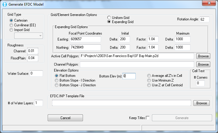
An expanding grid is simply a variable spaced Cartesian grid that expands in all directions from a focal point. The form shown in Figure 1 shows the parameters needed for developing an expanding grid. The user must specify the coordinates of the focal point, the initial (smallest) delta X and delta Y's, the rate at which the user wants them to expand at and the maximum cell sizes. Specify an Active Cell Polygon to trim the cells to the desired model domain. The spatial limits of the grid are set either by the topographic data or the active cell polygon.
Figure 1 Cartesian gridding: Expanding & rotated grid.
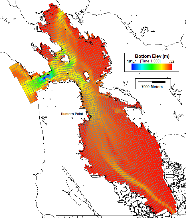
Figure 2 shows an example of the expanding grid developed for the San Francisco Bay. The focal point is just offshore from Hunters Point.
Figure 2 Expanding Cartesian grid example of San Francisco Bay.

