Overlay a Geo-referenced Map on a Digital Elevation Model in View3D
This page describes how to overlay a geo-referenced map on top of a terrain model or digital elevation model (DEM) in EFDC_Explorer. This is helpful for the user to make a realistic fly-through of an area of interest such as the Three Gorges Dam shown in the Figure 1.
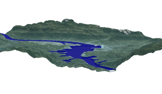 Figure 1 Three Gorges Dam fly-through.
In order to do that, the user need prepare a geo-referenced map and a Digital Elevation Model (DEM) of the area.
In this document, the three Gorges Dam will be taken as an example. Assuming that digital elevation data (.shape file), a geo-referenced map and a collada (.dae) true 3D model of the Three Gorges Dam in China are available.
- Generate grid for the three Gorges Dam region including upstream and downstream of the dam. The user can use CVLGrid to generate the grid
- Use EE to create the EFDC model for the dam with bathymetry assigned. No need assigning boundary condition.
- Open EE and load the three Gorges Dam model
To see geo-referenced map in EE, go to 2D Planview in EE then browse to background image file as shown in Figure 2 and Figure 3.
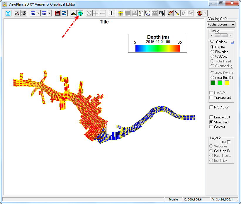 Figure 2 Load geo-referenced map in ViewPlan.
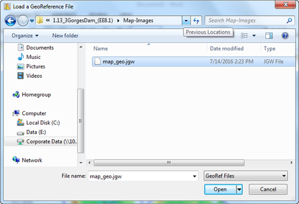
Figure 3 Browsing to geo-referenced map.
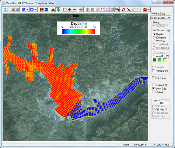
Figure 4 Geo-referenced map displayed in ViewPlan.
The user can see display of digital elevation data (*.shape file) in 3D View option of EE by go to 3D View Display Options ( ![]() ) on main menu then RMC on the legend, select Annotations Tab then Browse to the "contour_30m_z.shp" as an Overlay Files as shown in Figure 5 and digital elevation contour viewed in 3D as shown in Figure 6.
) on main menu then RMC on the legend, select Annotations Tab then Browse to the "contour_30m_z.shp" as an Overlay Files as shown in Figure 5 and digital elevation contour viewed in 3D as shown in Figure 6.
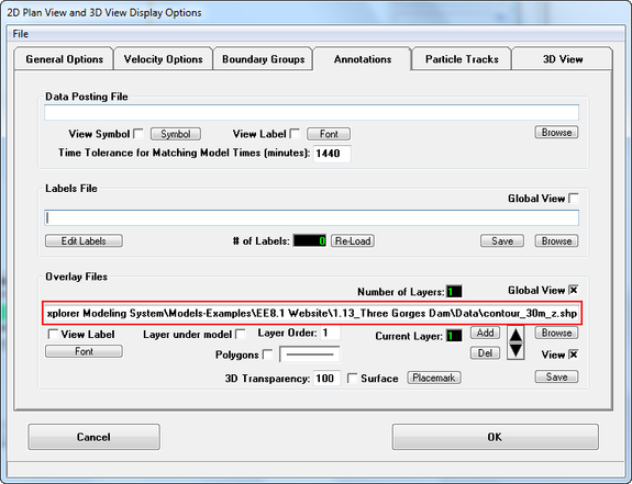
Figure 5 Load digital elevation data file.
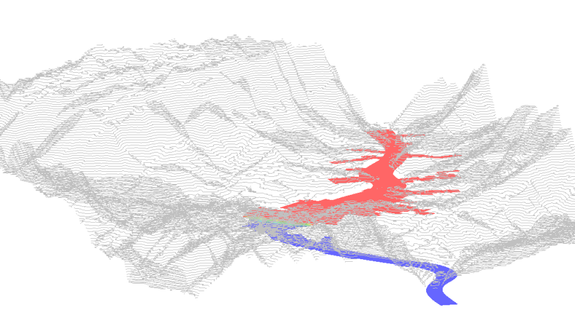
Figure 6 Digital elevation contour in View3D.
To start making the geo-referenced map top over this topography, click ![]() icon on main menu of EE. In View3D, click
icon on main menu of EE. In View3D, click ![]() then select 3D Geo/DEM Options as shown in Figure 7. Then 2D Planview and 3D View Display Options form will appear, the user select 3D View tab of the form then select 3D Geo/DEM Options sub-tab as shown in Figure 8.
then select 3D Geo/DEM Options as shown in Figure 7. Then 2D Planview and 3D View Display Options form will appear, the user select 3D View tab of the form then select 3D Geo/DEM Options sub-tab as shown in Figure 8.
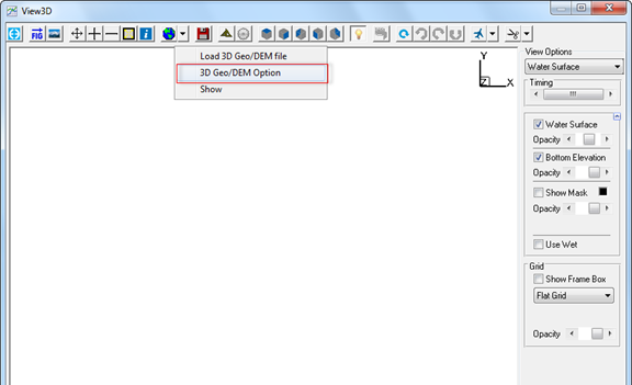
Figure 7 View3D form.
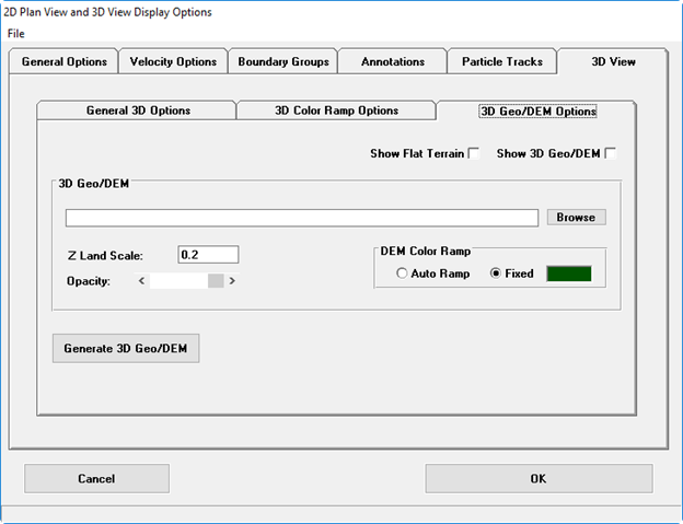
Figure 8 2D Plan View and 3D Display Options form.
At this stage, the user has two options, one is generate 3D Geo file, the other is generate DEM file from a terrain file (digital elevation data file):
- Generate 3D Geo file
The user clicks Generate 3D Geo/DEM button, 3D Geo/DEM Generation form will appear, the user select Generate 3D Georeference option, then browse to Geo File, next browse to Terrain File. After browsing to Geo File, the information of original image size will be displayed. Once the user can change the resolution of the Geo image by putting percentage (1 to 100) in Resize Image (%) box. Besides, the user can select Cell Size, Interpolation Radius optionally as shown in Figure 9. Finally the user click Generate button. Once, a form for importing raw data of terrain data file appear as shown in Figure 10. The user click Import button to proceed the process.
Geo File
The Geo File means that geo-reference files including *.geo and *.jpw. the extension *.geo generated by CVLGrid or EFDC_Explorer software and has been introduced in other pages in knowledge Base. The extension *.jpw generated by ESRI software like ArcMap, ArcGIS)
Terrain File
The Terrain File means that the ASCII file (*.txt, *.dat, *.xyz etc) contains three columns, the first and the second columns is Easting and Northing coordinates, the third column is elevation.
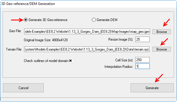 Figure 9 3D Geo-reference/DEM Generation form (1)
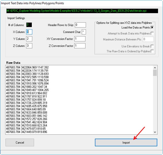 Figure 10 Import Terrain Raw Data form.
After the process of Importing terrain data file completed, a Save 3D Geo-reference File form appear, the user should name the file and select folder directory to put the file, then click Save button as shown in Figure 11. The process to generate 3D Geo-reference file done.
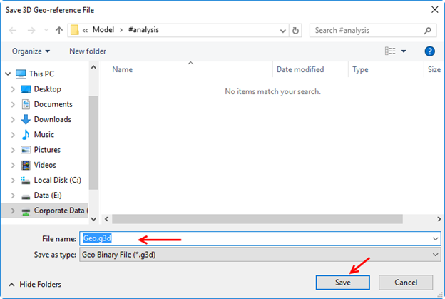 Figure 11 Save 3D Geo-reference File form.
2. Generate DEM file
In 3D Geo/DEM Options form, the user select Generate DEM option, then browse to Terrain File. Once the user can change the Cell Size, Interpolation Radius optionally as shown in Figure 12. Finally the user click Generate button. Similarly to generate 3D Geo-reference file, a form for importing raw data of terrain data file appear as shown in Figure 10. The user click Import button to proceed the process.
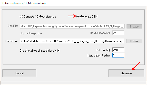
Figure 12 3D Geo-reference/DEM Generation form (2).
After the process of Importing terrain data file completed, a Save DEM File form appear, the user should name the file and select folder directory to put the file, then click Save button as shown in Figure 13. The process to generate DEM file completed.
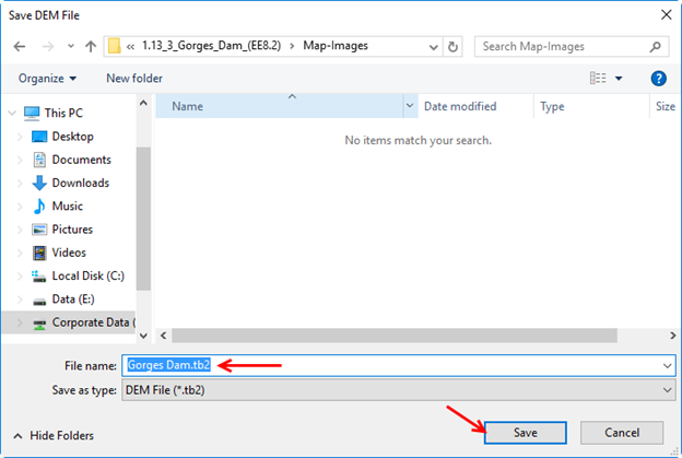
Figure 13 Save DEM File form.
3. Load 3D Geo/DEM file
When the 3D Geo-reference file or DEM file are available, the user now can load them. To load these files, the user browse to 3D Geo-reference file (*.g3d) or DEM file (*.tb2), then check on Show 3D Geo/DEM box as shown in Figure 14. Figure 15 shows a 3D Geo-reference file loaded. When the file 3D DEM loaded, in DEM Color Ramp, the user can choose either Auto Ramp or Fixed for displaying. Figure 16 shows a 3D DEM file loaded with fixed color ramp and Figure 17 shows a 3D DEM file loaded with auto color ramp.
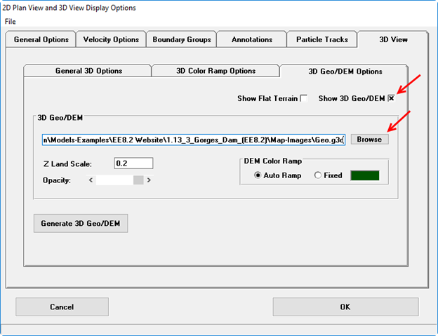
Figure 14 Load Geo/DEM File form.
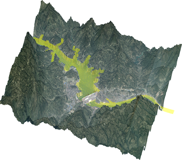
Figure 15 A 3D Geo-reference file loaded.
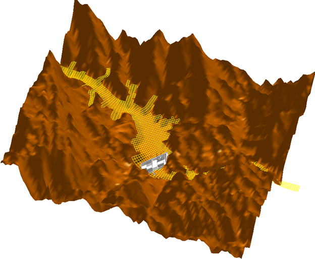
Figure 16 A 3D DEM file loaded with fixed color ramp.
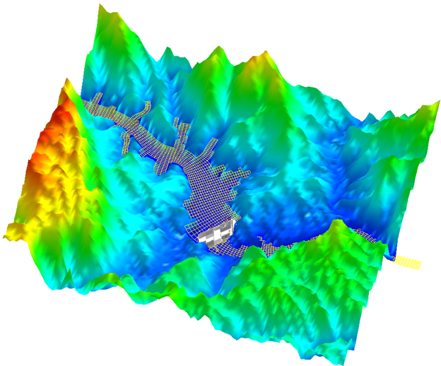
Figure 17 A 3D DEM file loaded with auto color ramp.