West Lake Toxics Model (Level 2 Step-by-Step Guidance)
- Kester Scandrett
- Duy Pham
1 Introduction
The toxics model is built based on a sediment transport model which can be downloaded from our website.
This tutorial document will guide you how to setup a Toxics Model base on West Lake example. It is supposed that the sediment transport model of West Lake has been set and that toxics will be added to this model.
2 Generate a Toxics Model
Open the West Lake Sediment Transport Model ( See Figure 1)
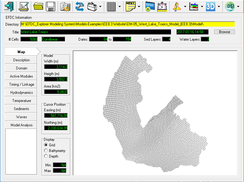
Figure 1. EE main form of West Lake Sediment Model.
2.1 Activate Toxics Modules
The user go to Active Modules tab, check on boxes to activate toxics ( See Figure 2), the Toxics tab will be added to the left-side tab.
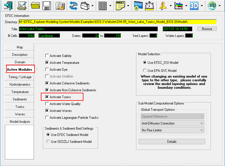
Figure 2. Activate Toxics Module.
2.2 Set Toxics Options
Click Toxics tab on the left-side tab then click Modify button (See Figure 3). A form of Toxics and Sediment Bed Toxics Properties appear, the user put the number of Toxics.
Put number of toxics = 3 then press button from keyboard then click OK button to proceed process ( See Figure 4).
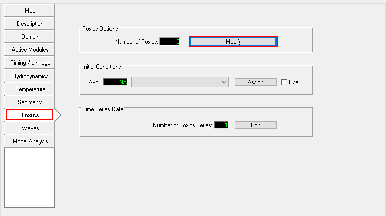
Figure 3. Editing Toxics Module (1).
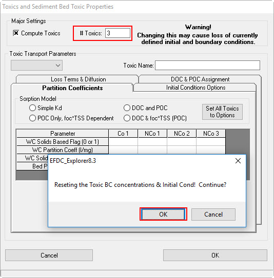
Figure 4. Editing Toxics Module (2).
Three toxic transport parameters will be created from Toxic 1 to 3 and each toxic parameter will have a corresponding name in Toxic Name box. The user can put a desired name for each toxic parameter ( See Figure 5)
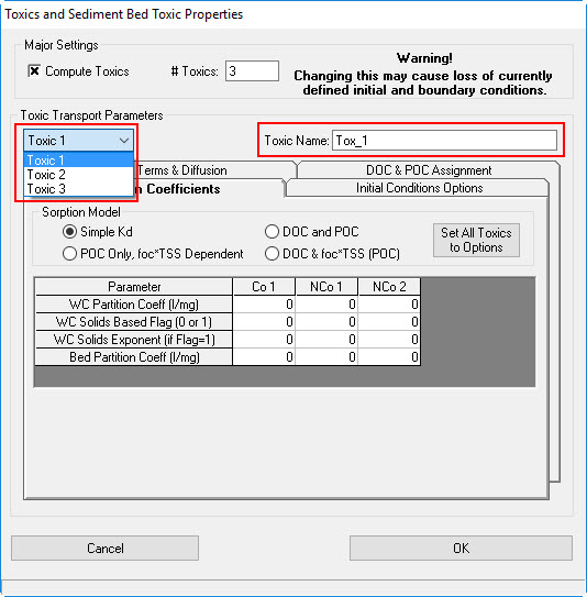
Figure 5. Editing Toxics Module (3).
Partition Coeffcients Tab
Select Toxic 1, put name as "Pesticides" in Toxic Name. Select DOC & foc*TSS (POC) option. Enter values for two table forms as shown in Figure 6.
Do similarly to Toxic 2 and Toxic 3 as shown in Fig. 7 & 8.
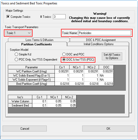
Figure 6. Toxic 1 Properties.
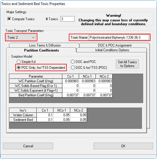
Figure 6. Toxic 2 Properties.
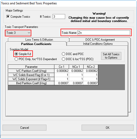
Figure 6. Toxic 3 Properties.
Loss Terms & Diffusion Tab
Figure 7 shows the tab for the Loss Terms & Diffusion of the Toxics properties option. In this tab the user may specify various parameters settings. Note that number of columns in the table form is equal to number of toxics. Put parameters' properties for three toxics as shown in Figure 7.
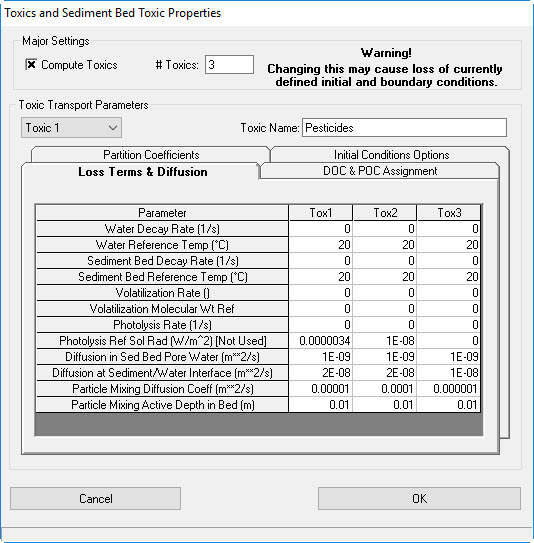
Figure 7. Toxics Loss Terms & Diffusion Properties.
DOC & POC Assignment Tab
Figure 8 shows the tab for the DOC & POC Assignment of the Toxics properties option. The user needs to assign concentration of DOC and POC in both water column and sediment.
Put options for DOC and POC as shown in Figure 8.
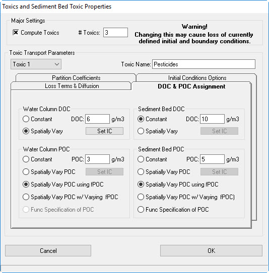
Figure 8. Toxics DOC and POC Assignment.
Initial Condition Options Tab
Figure 9 shows the tab for the Initial Condition Options of the Toxics properties option.
- Select Toxic 1
- Select ConstantWater Column & Bed
- Select Mass Tox/Sed (mg/kg)
- Put values 0.2 for Bed Toxic IC and 0.3 for Water Column Constant IC
In Toxic Transport Parameters
- Select Toxic 2. Put values 0.05 for Bed Toxic IC and 0.1 for Water Column Constant IC (See Figure 10)
- Select Toxic 3. Put values 0.025 for Bed Toxic IC and 0.05 for Water Column Constant IC (See Figure 11)
Finally, click OK button to complete.
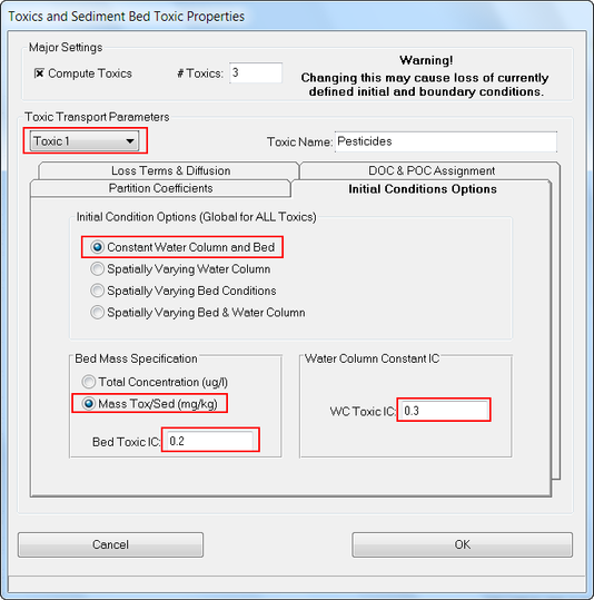
Figure 9. Toxics IC Options: Toxic 1
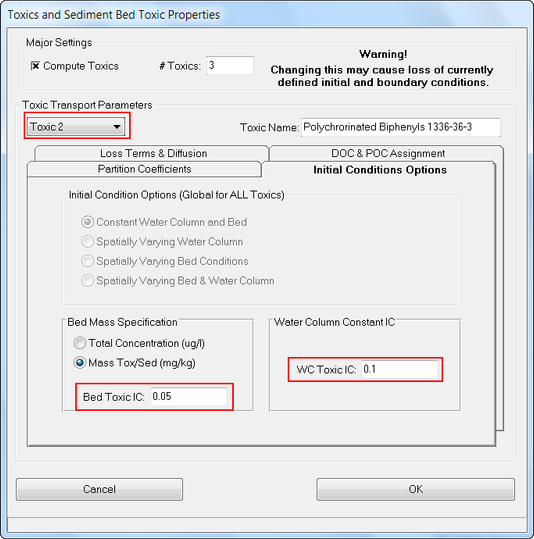
Figure 10. Toxics IC Options: Toxic 2
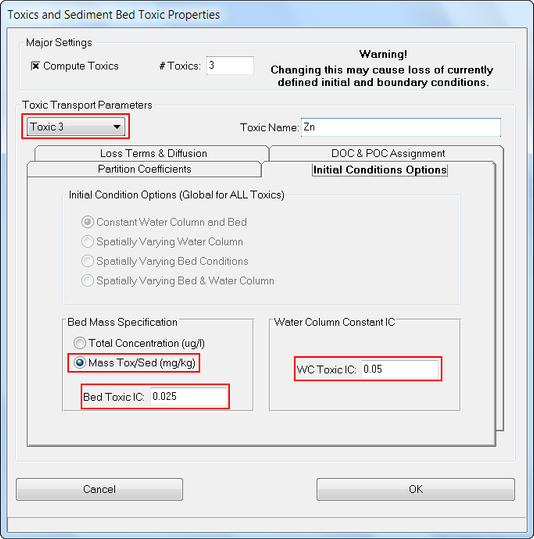
Figure 11. Toxics IC Options: Toxic 3
2.3 Boundary Conditions for Toxic
2.3.1 Set Time Series
- Select the Domain | Boundary Conditions (Figure 12)
- Click the Edit (E) button
 to edit the Toxics boundary (Figure 12)
 - Click up/down arrow to select Current Group is 1 ( mean Toxic 1) (Figure 13)
- Enter =1 in the Number of Series into the box (Figure 13)
- Fill timeseries data of toxic 1 as shown in (Figure 13)
- Click up/down arrow to select Current Group is 2 ( mean Toxic 3) (Figure 14)
- Fill timeseries data of toxic 1 as shown in (Figure 14)
- Click up/down arrow to select Current Group is 3 ( mean Toxic 3) (Figure 15)
- Fill timeseries data of toxic 3 as shown in (Figure 15)
- Click OK to finish editing the Toxics boundary time series.
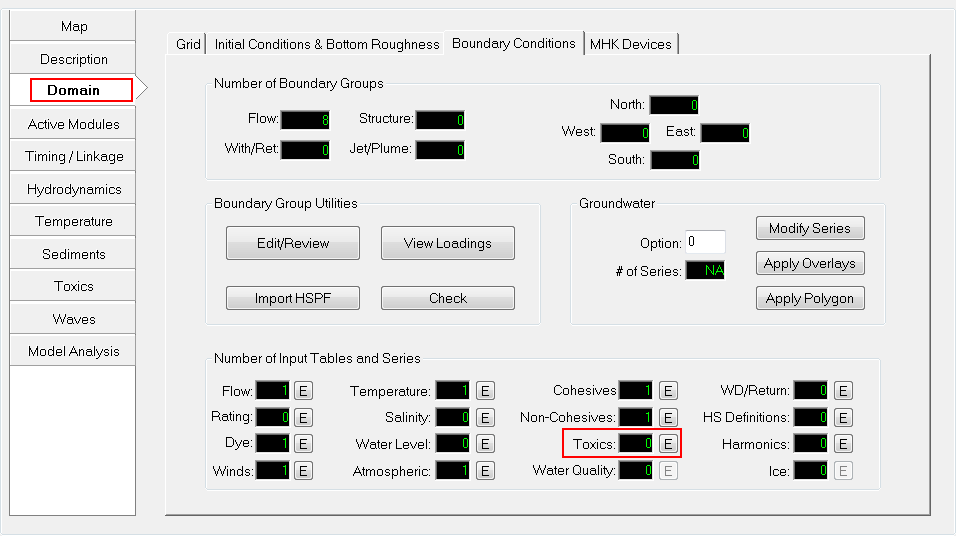
Figure 12. Toxics boundary conditions.
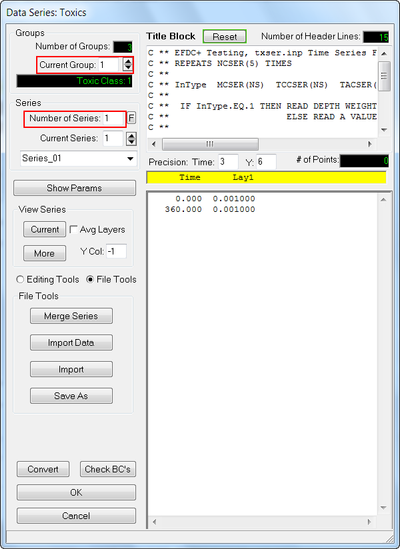
Figure 13. Data series for Toxic 1.

Figure 14. Data series for Toxic 2.
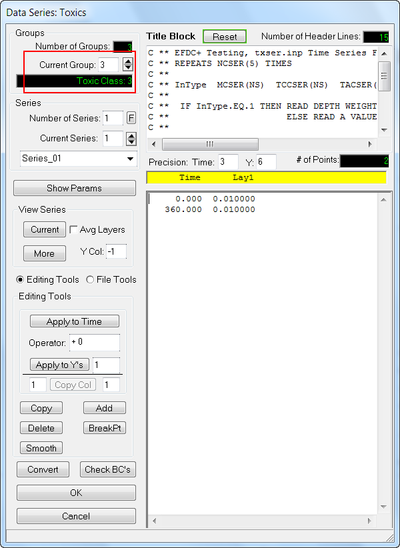
Figure 15. Data series for Toxic 3.
2.3.2 Assigning Boundary Condition
In order to assign the boundary, the following steps should be taken;
- Select the Domain | Boundary Conditions | Edit/Review (Figure 16).
- The Boundary Condition Definition/Groups form appears (Figure 17). Select "Cong Do" then click Edit button or just double-click on "Cong Do" (Figure 17).
- The Modify/Edit Flow BC Properties form appears (Figure 18). Click down arrow to select Series_01 for Toxics then click OK button (Figure 18).
- Repeat from step 1-3 for the other BCs left (e.g Giay TB, Ly Tu Trong etc.)
- Go to Domain | Grid, enter number of water layer = 3 then press enter key on the keyboard (Figure 19).
- Save model again then click Run EFDC button.
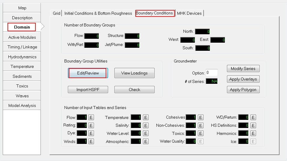
Figure 16. Edit Boundary Groups (1).
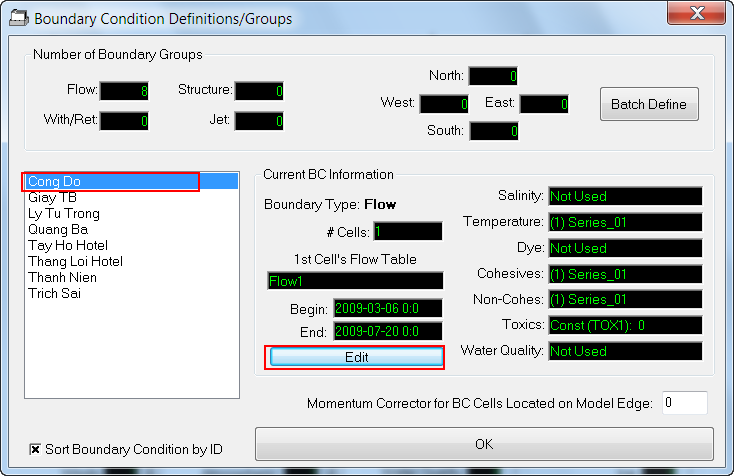
Figure 17. Edit Boundary Groups (2).
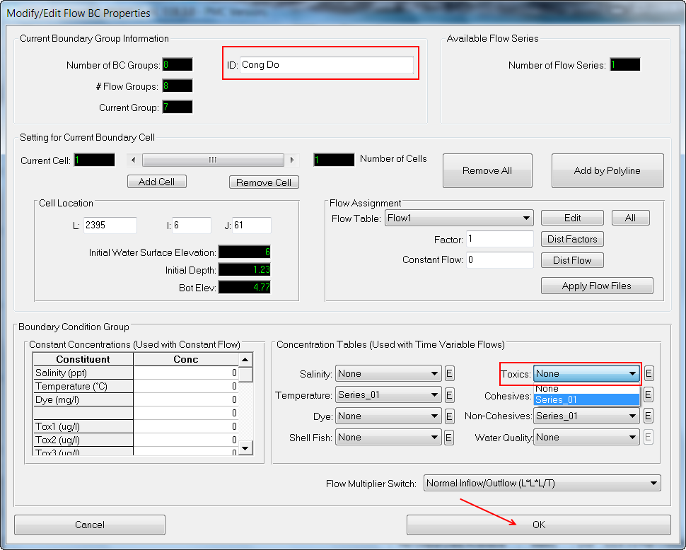
Figure 18. Assign Toxic Timeseries for "Cong Do".
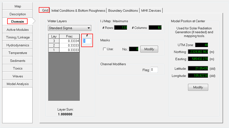
Figure 19. Set # of Water Layers for Model.