Withdrawal/Return BC Editor
EFDC_Explorer fully supports the withdrawal/return flow boundary condition of EFDC. The user interface for the withdrawal/return boundary condition editor is shown in Figure 1. As shown in the Time Control drop-down menu, EE allows the operation of withdrawal/return structures using time-series of flow (and constituent rises), as well as operation of the structures based on operational rules.
The user may specify the location of the withdrawal and return cells directly for each cell in the group in the Withdrawal Cell and Return Cell frames.
In the past EFDC did not allow the specification of the rise/fall for the water quality constituents. A “0” rise was always assumed. EFDCPlus was modified to allow the rise/fall for each water quality constituent to be specified, if using the time series option (i.e. QWRS.INP file). The constant rise/fall feature is only available for the original set of EFDC parameters of salinity, temperature, dye, toxics and sediments. These may be set in the W/R Flow and Concentration Rise/Fall Settings frame.
The user may also specify the momentum options for the withdrawal and return cells in the bottom frame. Use the drop down menu to select momentum flux to be ignored, or positive or negative in the U and V faces. The user may also set the momentum width for both withdrawal and return flows. In the case of the return flow the user may also set Return Flow Horizontal Angle.
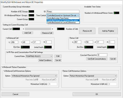
Figure 1 Boundary Condition Settings – Withdrawal Return.
With release of EE8.4 the W/R boundary condition has been modified to allows the operation of the structures based on operational rules. This has been implemented in an approach similar to that of the rule-based operations of sluice gate for hydraulic structures. One purpose of this enhancement is to allow the user to simulate rule-based pumps. It should be noted that at this stage this feature only acts on the flow series, and maintains the concentrations as constant i.e. there is no rise or fall for the WQ constituents.
The interface for the withdrawal/return boundary condition setup for a based on control rules rather than a time series is shown in Figure 1. The two control rule approaches require the user to configure rules for the structure. These rules are set in the W/R Flow and Concentration Rise/Fall Settings | Control Rules. Here the user may edit existing rule or create new ones as well as set the initial conditions
Figure 2 shows the settings for the rule-based withdrawal/return boundary. In this case a pumping station has been configured using the withdrawal/return boundary conditions. The approach is similar to that described for rule-based sluice gate operations: the user configures the number of sets of rules, and uses the up and down arrows to select the Current Rule set. Each set can have a number of different triggers, in this case two. The triggers are determined by the control value. This is the upstream elevation, or the difference in upstream and downstream head, depending on which option the user has selected.
EE uses the “state” of the structure to allow the user the high level of control required to simulate realistic scenarios. The logic of the process is that if the state of the structure is “1” then it is on, discharging the Flow Discharge set. This will continue from that trigger level until it reaches another trigger level. When a trigger is reached with state of “0” the pump will stop, and flow changes to the new Flow Discharge. The prevent instability in the system with sudden turning on and off of large flow rates within one time step, EE allows the user to set a rate of increase and decrease of the flow discharge with the Rate variable, in cms/minute.
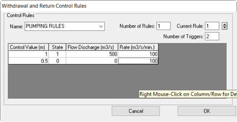 Figure 2 Withdrawal/Return BC: Control rules settings.
Figure 3 demonstrates the effect of the operation of the pumping station. In many cases the user will configure a simple system as described here. In this case it would seem the “state” setting is redundant as the pump is simply on or off. However, in some more complex systems there may be two or more pumps at a particular location. These may be configured as lead and lag pumps, with the lead pump turning on at a low water level and lag pump only turning on at a higher level. In these cases the user may want both pumps to stay on even when water level drops below the trigger level of the lead pump. For this reason the “state” setting is required to fully simulate the complexity of the system.
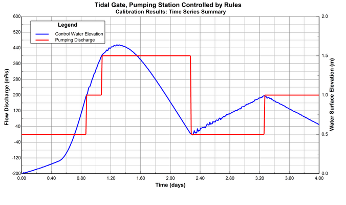 Figure 3 W/R boundary condition pump example.