For users familiar with EE8 and its earlier versions, there are a number of new conventions to be learned for using EE10. This section provides a general overview of the EE10 GUI. Detailed descriptions of different forms used in this section can be found in the relevant hyperlinks. EE10 also provides online help by pressing F1 on the main GUI. Pressing F1 on the main GUI opens the EE10 Knowledge Base in a default browser and F2 opens the list of shortcut keys.
EE10 Main Form
The main form for EE10 is shown in Figure 1 below. The numbered items in red in Figure 1 are referred to in the subsequent text. Similar pattern has been used in the entire knowledge base. The items displayed that are of immediate importance are the Main Menu (1), Main Toolbar (2), Model Report Bar (3), Model Control Form (4), 2DH View (5) and View Layer Control (6). In the sections below, the Model Control Form and the View Layer Control of the 2DH View are briefly described. Existing models may be opened in a manner similar to that of EE8.5; dragging and dropping an EE model folder or file into the main form, or by using the open button in the main toolbar.
Similar to EE8, EE10 allows multiple instances of application to be open at the same time. However, unlike EE8, multiple models can be opened in the same window at the same time. As described later, this capability makes comparison with multiple models easier. The title of the active model is displayed in the Model box in the Model Report Bar (3). Any form which is currently selected has a Title that is not grayed out (4). Title of other forms are grayed out. Windows may be minimized as seen at the bottom of the main form (7). The bottom of the main form also informs the user of the status of the current window (8).
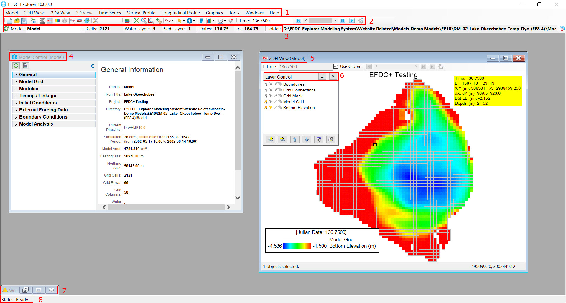
Figure 1. EFDC_Explorer10 Main Graphical User Interface.
Model Control Form
EE10 primarily revolves around the Model Control Form as shown in the Figure 2. This form provides a tree-structure for navigation of the form and turning on and off modules (sub-models), setting initial conditions, configuring modules, building time-series for external forcings, setting the boundary conditions, and setting model analysis and calibration options.
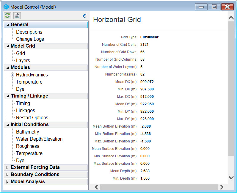 Figure 2. Model Control Form.
Left Mouse Click (LMC) on an item displays the information about the selected item. This is shown in Figure 3 where a report on the model grid is displayed.
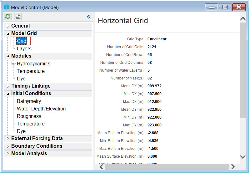
Figure 3. Model Control Form with LMC.
A right mouse click (RMC) displays options for editing the settings, initial conditions, or editing time series. The exact options displayed depend on the item selected. The options for Settings, Initial Conditions and Time Series are displayed with a RMC as shown in Figure 4. Details on how these options are used are provided in the Model Control Form section.
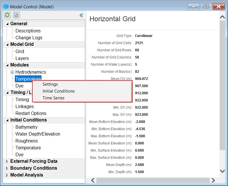 Figure 4. Model Control form with RMC on sub-item.
In some cases, RMC on an item in the tree will immediately open a form rather than provide options. For example, modules may be turned on and off by RMC on the Modules header in the Model Control form as shown in the Figure 5.
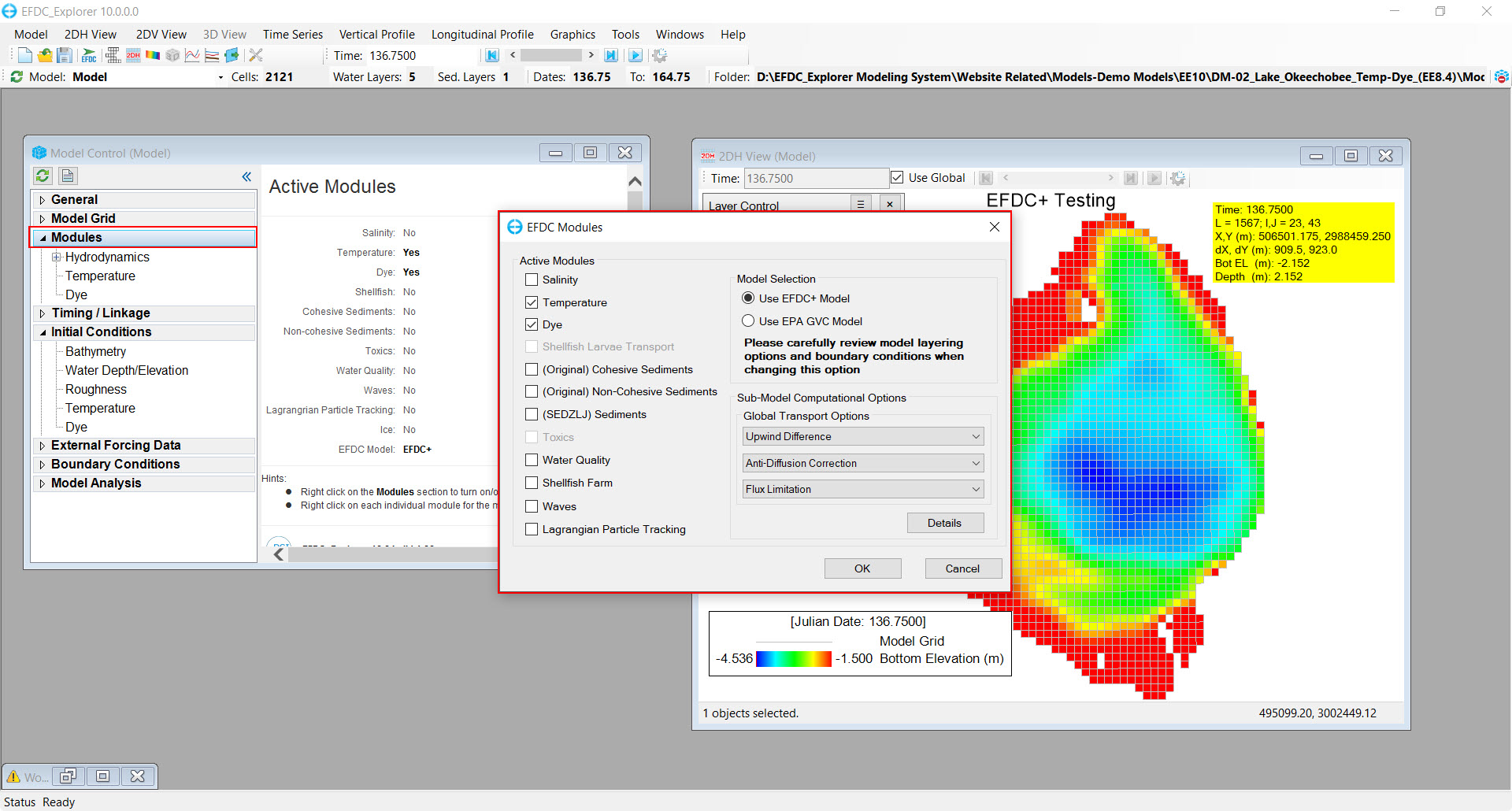
Figure 5. Turn on and off modules in the EFDC Modules form.
One of the main navigation options in EE10 is the plan view, called 2DH View (called ViewPlan in EE8.5) which is accessed from the main toolbar (2DH button) or the main menu (2DH View menu item). Navigation of the 2DH View is primarily governed by the Layer Control form shown in Figure 6 . By default, certain layers such as the model grid and the bottom elevation, will be displayed. The light bulb icon indicates whether a layer is displayed (on) or not displayed (off) (1). RMC on a layer provides a number of options including Properties to set the display properties. To add a new layer, select the Add a New Layer button (2). The user may then select from the 2DH View Option form from the drop-down list for the primary group, which includes options such as water level, boundary conditions, and water column (3). A sub-option for the parameter type should also be selected from the drop-down list. Select Add to add this to the 2DH View. Directly adjacent to the light bulb are the arrow, pencil, and tag icons. These allow the user to select, edit, and modify labels for a layer.
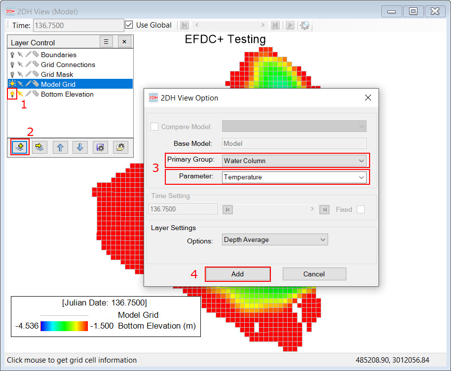 Figure 6. Select parameters to display in 2DH View.