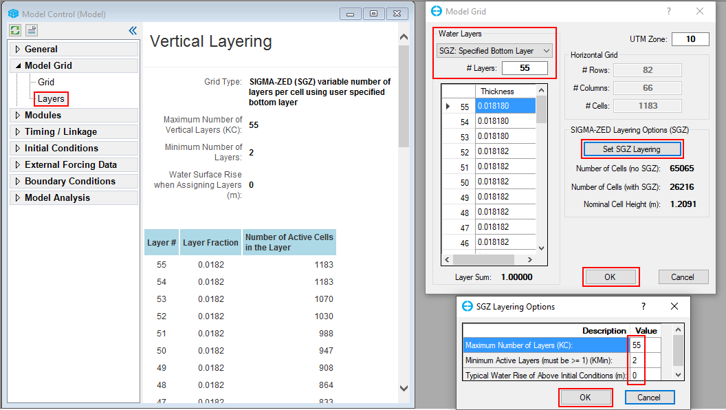
The Layers sub-menu summarizes the vertical layering in the grid. RMC on this menu item provides the options by which the user may configure the vertical layering system, as shown in Figure 1. Here, the user can select the Sigma Zed (SGZ) vertical layering option, which is implemented with EFDC+ alongside the previous option of Standard Sigma grid (SIG). In the Water Layers form the user can set the number of layers and access a drop-down menu option for the type of layering used in the model. These layering options are described in more detail below.
Figure 1. Model Grid menu: Layers
Standard Sigma Stretch Grid
The Standard Sigma option for water layers is the original EFDC option. When this is selected, the SGZ options are not displayed.
The table in the Water Layers frame shows the primary water layer settings (KC = the number of water layers) and the distribution of the relative layer thicknesses.
The relative thicknesses must add up to 1 (or very close). EFDC+ Explorer checks this for the user. EFDC+ Explorer will automatically divide the water layers into equal fractions based on the number of layers specified by the user. Note that layer 1 is the bottom-most layer and that the highest layer number is the surface layer (i.e. KC).
A very useful feature during preliminary testing of a model application is the rapid adjustment of layering simply by changing the number of layers. EFDC+ Explorer then reallocates the layering based on the new KC and then adjusts all the boundary conditions to reflect this change. Use this feature with care, but it has been used on many applications and found to work well.
Sigma-Zed Vertical Layering
EFDC+ Explorer implements DSI's improved version of the EFDC code, the EFDC+_SGZ. DSI has developed this version to deal with pressure gradient errors that occur in models that have steep changes in bed elevation. This new version of the code is called the Sigma-Zed code, or EFDC_SGZ. This version contrasts with the conventional sigma stretch version (SIG) of the EFDC code in terms of vertical layering in the model. SIG uses a sigma coordinate transformation in the vertical direction and uses the same number of layers for all cells in the domain. To accommodate the varying depths over the model domain in the SIG approach, the thickness of the layers vary from cell to cell, but the number of layers and fraction of depth for each layer are constant. SIG approach introduces a well-known error in the density gradient terms, otherwise known as the pressure gradient error (Mellor et. al. 1994). These errors are most pronounced in regions with steeply varying bathymetry.
The new vertical layering approach (SGZ approach) developed and applied to the EFDC model is computationally efficient and significantly reduces pressure gradient errors. In the EFDC_SGZ model, the vertical layering scheme has been modified to allow for the number of layers to vary over the model domain. Each cell can use a different number of layers, though the number of layers for each cell is constant in time. As with the Sigma Stretch approach, the thickness of each layer varies in time to accommodate the time-varying depths for which reason the user must set the maximum and minimum number of layers (see Figure 4 below). The z coordinate system varies for each cell face, matching the number of active layers to the adjacent cells. The new version is computationally more efficient than a similarly configured Sigma Stretch grid, thus making models with 20 to 50 layers or more practical for typical projects.
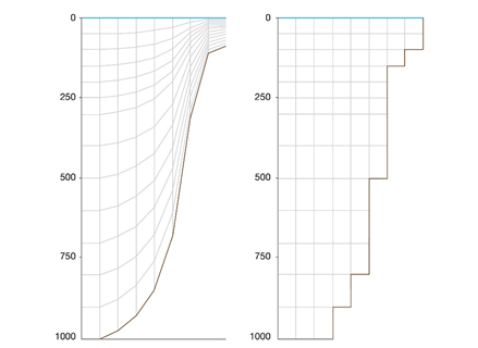
A comparison of SIG and SGZ grids is shown in Figure 2.
Figure 2. Vertical grids for Sigma stretch (left) and Sigma-Zed (right).
The model grid specification as SIG or SGZ can be made in the main form of EE from the Model Grid menu and RMC on Layers menu item, which displays the form shown in Figure 3. The first option Standard Sigma is the conventional gridding scheme of the EFDC model.
The three options for implementing SGZ option in EE are Specified Bottom Layer (GRIDV=1), Uniform Layer Thickness (GRDIV=2), and Specified Thickness from Top (GRIDV=3), each of which is described below.
Figure 3. Model Grid: Water layering options.
Specified Bottom Layer (GRIDV=1)
In Specified bottom layer, the layer thickness of the adjacent cells in the vertical does not align in the same plane. Maximum depth in the model is first calculated, and the maximum layer thicknesses are determined based on maximum depth. Zonation can be applied using this option. This option is suited for coastal systems with significant differences in water surface elevation in different parts of the domain. Like all SGZ options, it is designed for stratified systems and systems with rapidly changing bed elevation.
Uniform Layer Thickness (GRIDV=2)
For this option, the layer thickness of a given cell is typically the same size as the neighboring cell. The bottom layer thickness can vary from 20-120% of the overlying layer. The maximum thickness is first calculated throughout the domain. Thickness at each layer for the cell with maximum depth is then calculated by multiplying DZCK with maximum thickness. Zonation cannot be applied in Uniform Layers option. Uniform Layers is suitable in quiescent systems where there is very little external flow influence, such as lakes with steeply sloping sides and small inflows.
When computing buoyancy integrals in the model, there are differences between layer thickness and the difference between elevation. Using the uniform layer thickness, the differences between layer thicknesses are very small except for the regions with minimum sigma layers.
The SGZ Layering Options form provides the user with the option of specifying the maximum and minimum layers to be used in the model, as shown in Figure 4. The Typical Rise Above Initial Conditions option may be utilized to address the bathymetric variations. While it can be utilized for all the Simga Z options, it was specifically designed for use with SGZ =2. The purpose of this function is to raise or lower the depth of the water level in the lake to a more typical value compared to the initial conditions to allow for more appropriate layer splits. For example, the initial condition of a lake may be a meter below the typical value, so the user would set the typical water rise value to 1, so that the layer splits are configured based on typical condition. In a tidal system, it would make sense to make this value so that it is close to the mean tide water level. The user can also lower or raise over a certain area by using a polygon.
After selecting Set SGZ Layering and OK, the layers are all automatically updated to the Sigma Stretch layering.
Figure 4. SGZ Layering Options.
Sigma-Zed Specified Thickness from Top (GRIDV=3)
This option allows the user to specify layer thickness precisely and not just provide an approximate value for each layer. As a result, the user has control over the initial thicknesses. Further adjustments were applied to EEMS to manage isolated cells at the bottom layer. Cells that are disconnected from all other cells in all four directions exhibit instability. Consequently, EE will automatically eliminate these isolated cells and merge them with the cells above. This SGZ is an appropriate choice when modeling a gate-based scenario. In addition, dividing layers by depth provides considerable flexibility when simulating hydraulic structures, as users can directly specify the desired depth to be set based on the project's parameters as well as the water level around the modeled area.


