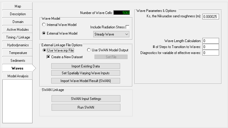
This external wave model option allows the user to import wave parameter fields from other common wave models. The Steady Wave /Unsteady Wave option corresponds to the types of waves being imported into the EFDC model. The steady wave option means that the waves are not changing with time so the EE will not read the WAVETIME.INP file. The unsteady wave option does require the WAVETIME.INP input file. The setting in the frame reflects the way the user has imported the external waves.
Figure 1 Waves Tab: External Linkage to SWAN Wave Model.
There are four different sub-options to take into account while assigning the wave parameters into EFDC model as following;
(1) Use Wave Input File
If the user already has a WAVE.INP file (of format shown in Appendix B 12), then the data is imported first time by checking the New Dataset checkbox. If a WAVE.INP has already been imported then the import options described below are greyed out until the New dataset box is selected.
(2) Import Existing Data
EE imports an available WAVE.INP file from another project into the current project. It should be noted that two projects must have exactly the same grids.
(3) Set Spatially Varying Wave Inputs
This is an option for EE7 and earlier and it is not advised be used due to the longer time required to prepare the input data. For ISWAVE=1 and ISWAVE=2 the external model results may be imported into EFDC_Explorer which will generate the required wave linkage file, depending on the ISWAVE option. Figure 2 shows the main import/field interpolation form for the wave parameters for ISWAVE=2. The user must match the input data file (which should be in XYZ format tab, space or comma delimited) to the parameter specified on drop down list Wave Field Parameters (options shown in adjacent inset). The user can either have wave height (2*wave amplitude) or wave energy. EE will compute the one from the other. The user has the option of using a polygon to select which EFDC cells will be used for the assignment. If a Poly file is not selected, then the assignment operation will be for the entire model domain. EE interpolates and converts the wave model results into the formats needed for EFDC. The interpolation process has two options, nearest neighbor interpolation or cell averaging. Cell averaging should be used when the imported data is denser than the EFDC model grid (this will usually be the case). The nearest neighbor interpolation scheme should be used if the imported data is sparser than the EFDC model grid.
Figure 2 Wave generated turbulence, import data form.
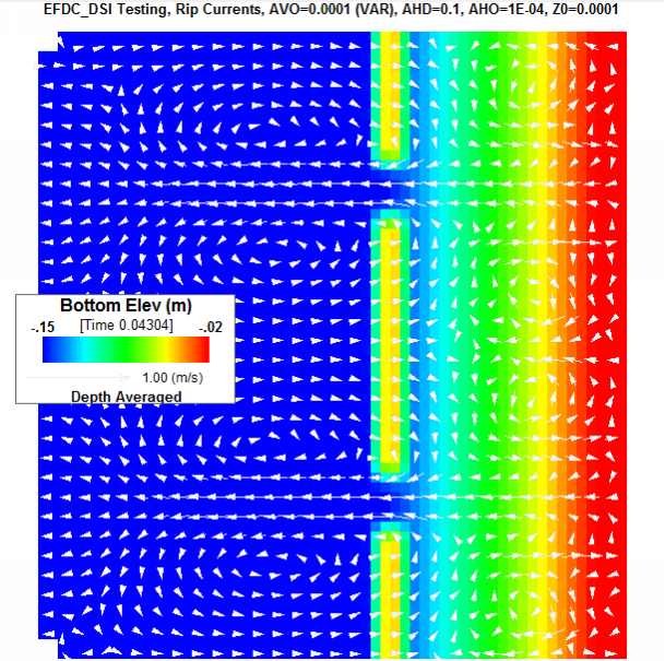
DSI has extensively tested and verified the ISWAVE=2 option for both EE and EFDC using the RefDif/ShoreCirc modeling of rip tide currents (Svendsen, et. al., 2000). Figure 3 shows EFDC_DSI model results for the rip tide test case. The velocity vectors (in white) have been overlaid on the bathymetry. The velocity pattern and magnitude are similar to what was computed by Svendsen.
Figure 3 Wave generated rip tide currents overlaid on idealized beach.
(4) Import Wave Model Results from SWAN
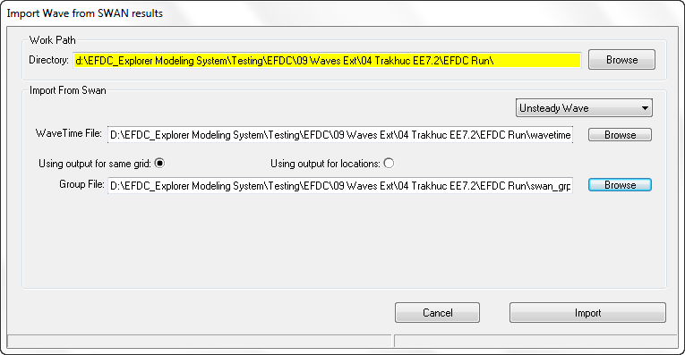
Currently EE only imports data from the SWAN wave model, however, it is anticipated that other models will be included at a later date. If the user chooses to import the SWAN output files through EE then the Import Wave Model (SWAN) button should be selected. This displays the form shown in Figure 4. The default Work Path is the current model directory. The user should browse to a different directory if they want to avoid saving over an existing WAVE.INP file.
In the Import from SWAN frame the user should first decide if they are using steady or unsteady waves with the dropdown box. If steady waves are used then then EE does not require the WAVETIME.INP file as the waves are at regular time intervals and the option to load this file is disabled. Alternatively, if unsteady waves are being used then then browse to the path for the SWAN model outputs and select the the wave time file (WAVETIME.INP). Next there are two options for SWAN input:
1. Using output for locations option requires the SWAN model to have same grid as the current EE model and uses the group file from SWAN, (SWAN_GRP.INP).
2. Using output for location option uses the data as x, y points. This option should be chosen when SWAN and EE use two different grids and wave data was exported at the locations (x, y) from the SWAN model. The latter option requires two input files: a location file and a table file. These should have been defined and saved out from the SWAN model.
Once these files have been selected the user should select the Import button. Two files will be created: WAVE.INP and WAVETIME.INP for the EFDC model run.
Figure 4 Waves Tab: SWAN Import function when using same grid as EE.


