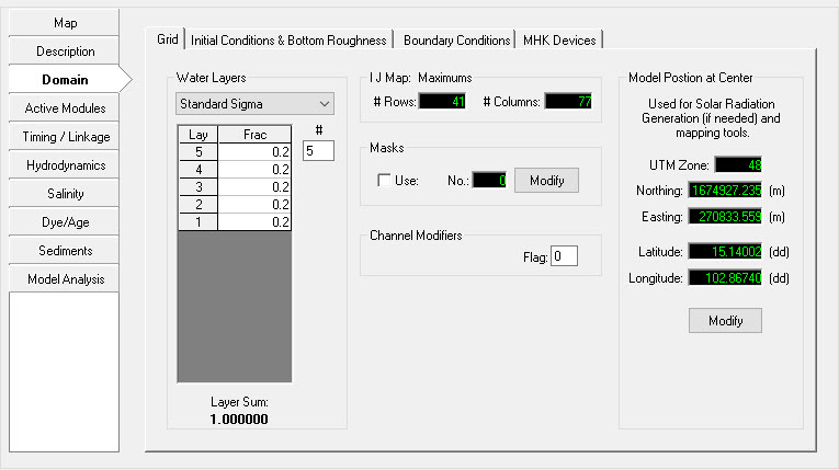
The Grid tab provides the options by which the user may set the vertical layering system as well as modify the horizontal grid , set masks, and also set the model position at its center as shown in Figure 1. The Sigma Zed (SGZ) vertical layering option is implemented with EFDC+ alongside the previous option of Standard Sigma grid (SIG). A dropdown drop-down option for the Water Layers is provided and each option the options described below.
| Anchor | ||||
|---|---|---|---|---|
|
Figure 1 Domain Tab: Grid
...
The Standard Sigma option for Water Layers is the previous option provided in all versions of EFDC_DSIEFDCPlus. When this is selected the SGZ options are not displayed.
...
Sigma Zed Vertical Layering
EFDC_Explorer8.0 now Explorer implements DSI's improved version of the EFDC code, the EFDC_DSI_SGZ. DSI has developed this version to deal with pressure gradient errors that occur in models that have steep changes in bed elevation. This new version of the code is called the Sigma Zed code, or EFDC_SGZ. This version contrasts with the conventional sigma stretch version (SIG) of the EFDC code in terms of vertical layering in the model. SIG uses a sigma coordinate transformation in the vertical direction and uses the same number of layers for all cells in the domain. To accommodate the varying depths over the model domain in the SIG approach, the thickness of the layers vary from cell to cell but the number of layers and fraction of depth for each layer are constant. SIG approach introduces a well-known error in the density gradient terms, otherwise known as the pressure gradient error (Mellor, et. al. 1994). These errors are most pronounced in regions with steeply varying bathymetry.
The new vertical layering approach (SGZ approach) developed and applied to the EFDC model is computationally efficient and significantly reduces pressure gradient errors. In the EFDC_SGZ model, the vertical layering scheme has been modified to allow for the number of layers to vary over the model domain. Each cell can use a different number of layers, though the number of layers for each cell is constant in time. As with the Sigma Stretch approach, the thickness of each layer varies in time to accommodate the time varying depths. The z coordinate system varies for each cell face, matching the number of active layers to the adjacent cells. The new version is computationally more efficient than a similarly configured Sigma Stretch grid, thus making models with 20 to 50 layers or more practical for typical projects.
A comparison of SIG and SGZ grids is shown in Figure 2.
...
The two options for implementing SGZ option in EE8 EE are a) Specified Bottom Layer and b) Uniform Layer Thickness. The second two options i.e., SGZ Specified Bottom Layer and SGZ Uniform Layer Thickness, are both SGZ model options with the following attributes.
Specified Bottom Layer
...
In Specified bottom layer, the layer thickness of the adjacent cells in the vertical do not align in the same plane. Maximum depth in the model is first calculated and the maximum layer thicknesses are determined based on maximum depth. Zonation can be applied using this option. This is the robust option and can be applied on any type of systems such as stratified systems, systems with rapidly changing bed elevation.
Uniform Layer Thickness
...
Layer thickness of the cell is mostly of the same size as the neighboring cell. The bottom layer thickness can be from 20-120% of the overlying layer. The maximum thickness is first calculated throughout the domain. Thickness at each layer for the cell with maximum depth is then calculated by multiplying DZCK with maximum thickness. Zonation cannot be applied in Uniform Layer Thickness option. Uniform Layer Thickness is suitable is quiescent systems where there are very little external flow influence such as lakes without steep sloping sides.
When computing buoyancy integrals in the model, there are differences between layer thickness and difference between elevation. Using the uniform layer thickness, the differences between layer thicknesses is very small except for the regions with minimum sigma layers.
The SIGMA ZED Layering Options form provides the user with the option of specifying maximum and minimum layers to be used in the model. After selecting Set SGZ Layering and OK, the layers are all automatically updated to the Sigma Stretch layering.
...
Care should be exercised in using channel modifiers as model instability is sometimes increased and mass balance errors can occur.
Model Position at Center
Latitude and longitude settings the center of model are accessed in Domain | Grid | Model Position at Centre as shown in Figure 1 above. These settings are required for EFDC+ to calculate solar radiation as well as mapping features in EE. The user should select the Modify button to update these values. If the user has not entered a UTM zone for the model the default will be UTM zone 10 and the Northing and Easting will be set to the model centroid. EE reads the UTM zone from C91 (netCDF settings) in the EFDC.INP and updates to the latitude and longitude are stored in C46C (atmospheric location and wind function coefficients). Northing and Easting values are calculated based on the UTM and lat/long values.
