The Grid tab provides the options by which the user may set the vertical layering system, set masks, and also set the model position at its center as shown in 2389722 Grid Tab#Figure 1. The Sigma Zed (SGZ) vertical layering option is implemented with EFDC+ alongside the previous option of Standard Sigma grid (SIG). A drop-down option for the Water Layers is provided and the options described below.
| Anchor | ||||
|---|---|---|---|---|
|
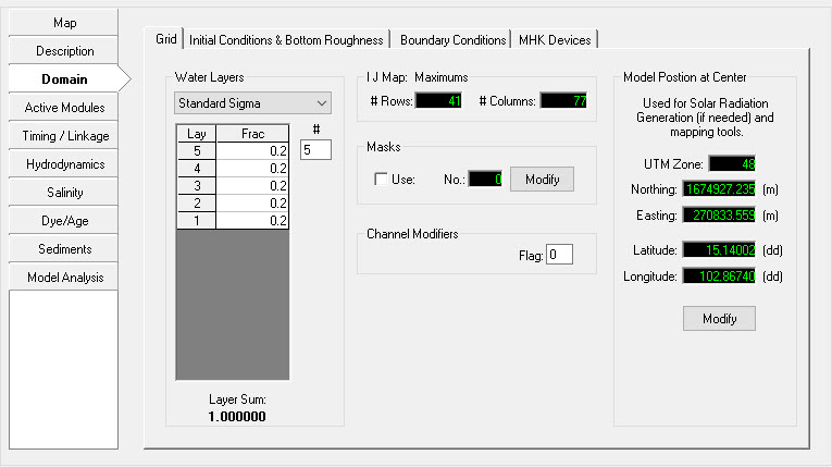
Figure 1 1 Domain Tab: Grid
Standard Sigma Stretch Grid
The Standard Sigma option for Water Layers is the previous option provided in all versions of EFDCPlusEFDC+. When this is selected the SGZ options are not displayed.
...
The relative thicknesses must add to 1 (or very close). EFDC_+ Explorer checks this for the user. EFDC_+ Explorer will automatically divide the water layers into equal fractions based on the number of layers specified by the user. Note that layer 1 is the bottom most layer and that the highest layer number is the surface layer (i.e. KC).
A feature here that is very useful during preliminary testing of a model application is the rapid adjustment of layering simply by changing the number of layers. EFDC_+ Explorer simply reallocates the layering based on the new KC and then adjusts all the boundary conditions to reflect this change. Use this feature with care, but it has been used on many applications and found to work well.
...
Sigma Zed Vertical Layering
EFDC
...
+ Explorer implements DSI's improved version of the EFDC code, the EFDC_DSI_SGZ. DSI has developed this version to deal with pressure gradient errors that occur in models that have steep changes in bed elevation. This new version of the code is called the Sigma Zed code, or EFDC_SGZ. This version contrasts with the conventional sigma stretch version (SIG) of the EFDC code in terms of vertical layering in the model. SIG uses a sigma coordinate transformation in the vertical direction and uses the same number of layers for all cells in the domain. To accommodate the varying depths over the model domain in the SIG approach, the thickness of the layers vary from cell to cell but the number of layers and fraction of depth for each layer are constant. SIG approach introduces a well-known error in the density gradient terms, otherwise known as the pressure gradient error (Mellor, et. al. 1994). These errors are most pronounced in regions with steeply varying bathymetry.
The new vertical layering approach (SGZ approach) developed and applied to the EFDC model is computationally efficient and significantly reduces pressure gradient errors. In the EFDC_SGZ model, the vertical layering scheme has been modified to allow for the number of layers to vary over the model domain. Each cell can use a different number of layers, though the number of layers for each cell is constant in time. As with the Sigma Stretch approach, the thickness of each layer varies in time to accommodate the time varying depths. The z coordinate system varies for each cell face, matching the number of active layers to the adjacent cells. The new version is computationally more efficient than a similarly configured Sigma Stretch grid, thus making models with 20 to 50 layers or more practical for typical projects.
A comparison of SIG and SGZ grids is shown in
...
| Anchor | ||||
|---|---|---|---|---|
|
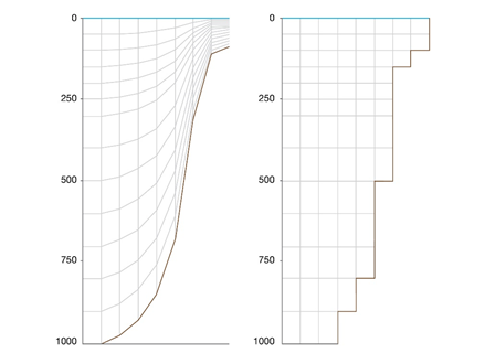
Figure 2 2 Vertical grids for Sigma stretch (left) and Sigma Z (right).
The model grid specification as SIG or SGZ can be made in the main form of EE from the Domain tab | Grid sub-tab as shown in
...
Grid Tab#Figure 3. The first option Standard Sigma is the conventional gridding scheme of EFDC model.
The two options for implementing SGZ option in EE are a) Specified Bottom Layer and b) Uniform Layer Thickness. The second two options i.e., SGZ Specified Bottom Layer and SGZ Uniform Layer Thickness, are both SGZ model options with the following attributes.
Specified Bottom Layer
In Specified bottom layer, the layer thickness of the adjacent cells in the vertical do not align in the same plane. Maximum depth in the model is first calculated and the maximum layer thicknesses are determined based on maximum depth. Zonation can be applied using this option. This is the robust option and can be applied on any type of systems such as stratified systems, systems with rapidly changing bed elevation.
...
| Anchor | ||||
|---|---|---|---|---|
|
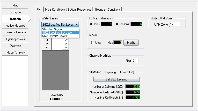
Figure 3 Domain Tab: Layering Options (SIG & SGZ)
Masks
In the Masks frame the Use check box enables the user to enable masks (zero thickness flow barriers) in EFDC. The MASK.INP file will then be required by EFDC. EFDC
...
+ Explorer can generate and modify masks using the Modify button as shown in
...
Grid Tab#Figure 4. The Create Masks utility does not automatically turn on the mask computation, it just generates the masks and writes the MASK.INP file. The user must manually click the mouse cursor inside the Use Masks check box to use the masks generated.
| Anchor | ||||
|---|---|---|---|---|
|
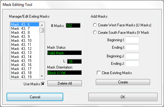
Figure 4 Mask Editing Tool.
...
The most flexible approach to create and edit channel modifiers is to:
turn on this option (i.e. ISCHAN=2),
enter the ViewPlan,
select Modchannel,
enable edit, and
use the right mouse click to add, delete or modify channel modifiers (i.e. "pipes").
Care should be exercised in using channel modifiers as model instability is sometimes increased and mass balance errors can occur.
Model Position at Center
Latitude and longitude settings the center of model are accessed in Domain | Grid | Model Position at Centre as shown in
...
Grid Tab#Figure 1 above. These settings are required for EFDC+ to calculate solar radiation as well as mapping features in EE. The user should select the Modify button to update these values. If the user has not entered a UTM zone for the model the default will be UTM zone 10 and the Northing and Easting will be set to the model centroid. EE reads the UTM zone from C91 (netCDF settings) in the EFDC.INP and updates to the latitude and longitude are stored in C46C (atmospheric location and wind function coefficients). Northing and Easting values are calculated based on the UTM and lat/long values.