...
Selecting the Edit button shown in Figure 2 opens the equation editor for the flow control type selected. Each hydraulic structure type is described further below. Note that for every equation, there is a check box to indicate whether or not to allow reverse flows. In terms of vertical layering, EFDC draws equally from all the layers not impacted by the structure.
Culverts
To assist the user define the input parameters for the culvert, a Definition Editor is provided as shown in Figure 3. This form can be accessed by clicking on Edit button in Figure 2. Here the user may define the Equation ID, allowing various culverts dimensions and type to be defined.
The user should select the Hydraulic Structure Type from the drop-down menu. In this case, the option chosen is "culvert". The user should then select the Cross-section type. Depending on the options chosen the image of the culvert will change to match the user's selection. The user can then specify the culvert dimensions in meters, including upstream and downstream elevations of the pipe, length of the pipe, Manning's roughness coefficient and diameter of the pipe as shown in Figure 3. The user may also import 3D structures to better visualize the hydraulic structures in EE8 as shown in Figure 4. An animation of an example culvert may be seen here.
| Anchor | ||||
|---|---|---|---|---|
|
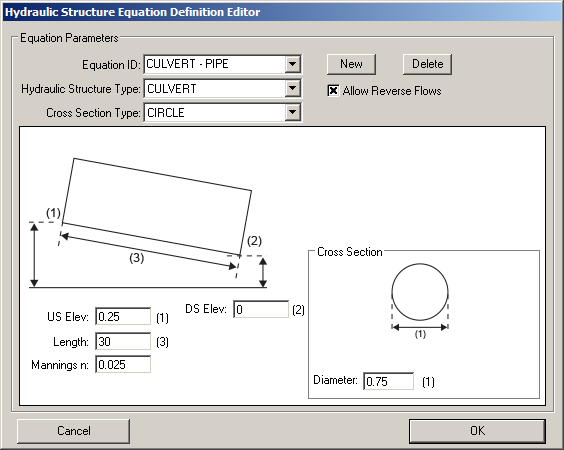
Figure 3 Hydraulic Structure Equation Editor: Culverts.
...
The user should select the Hydraulic Structure Type from the dropdown menu, in this case it is "sluice gate". The user should then enter the sluice gate dimensions, including sill elevation, height, width, super-critical weir flow, sub-critical weir flow, free sluice flow and submerged orifice flow parameters as shown in Figure 12. The user may also import 3D structures to better visualize the hydraulic structures in EE8 as shown in Figure 13. An animation of an example sluice gate may be seen here.
| Anchor | ||||
|---|---|---|---|---|
|
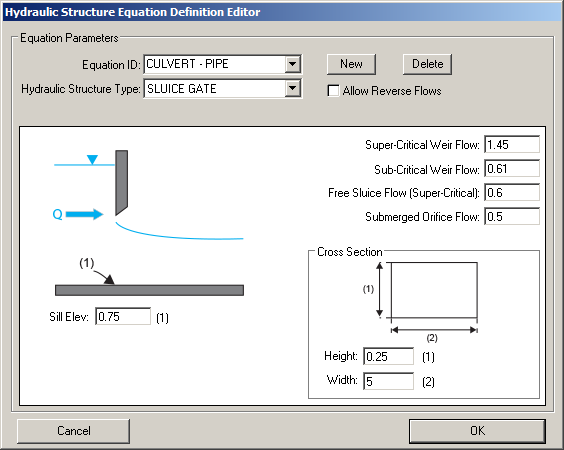
Figure 12 Hydraulic Structures Equation Definition: Sluice gate.
...