Insufficient observed data for inflow or outflow when establishing your reservoir can lead to unsatisfactory validation results when comparing observed water levels with those calculated in the model. In such situations, the Reservoir Water Balance tool proves valuable. It relies on the difference between observed and calculated water levels to generate a balanced inflow time series. Subsequently, utilizing this time series can result in significantly improved validation results.
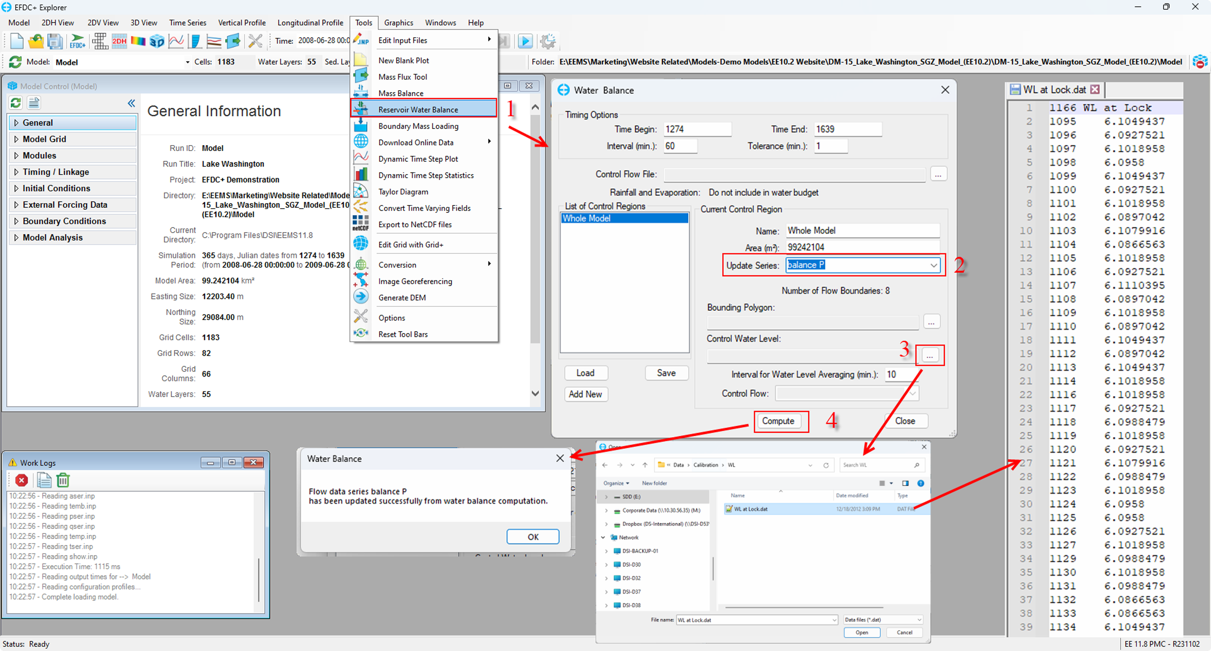
The Reservoir Water Balance tool can be selected from the Tool Tools menu, as shown illustrated in Figure 1.
...
Figure 1. Generate DEM.
Once the option is selected, the Water Balance form will appear as shown in Figure 2. From this form, the user can browse to control flow file from the Control Flow File. Once loaded, the user clicks on the Compute button.
...
...
. The Water Balance form will then be displayed. In this form, Timing Options can be configured or left as default.
In the Update Series options, choose a time series station that will be used to balance the water levels. This is shown in Figure 2 below, where the series Balance P has been selected. After selecting this time series station, a Control Water Level series should be chosen to serve as the observed water level. Please note that the import file for the Control Water level must be in the correct format (see Figure 1). When the Compute button is selected, a notification indicating successful computation will appear.
Figure 1. Reservoir Water Balance
Selecting a Time Series and Location
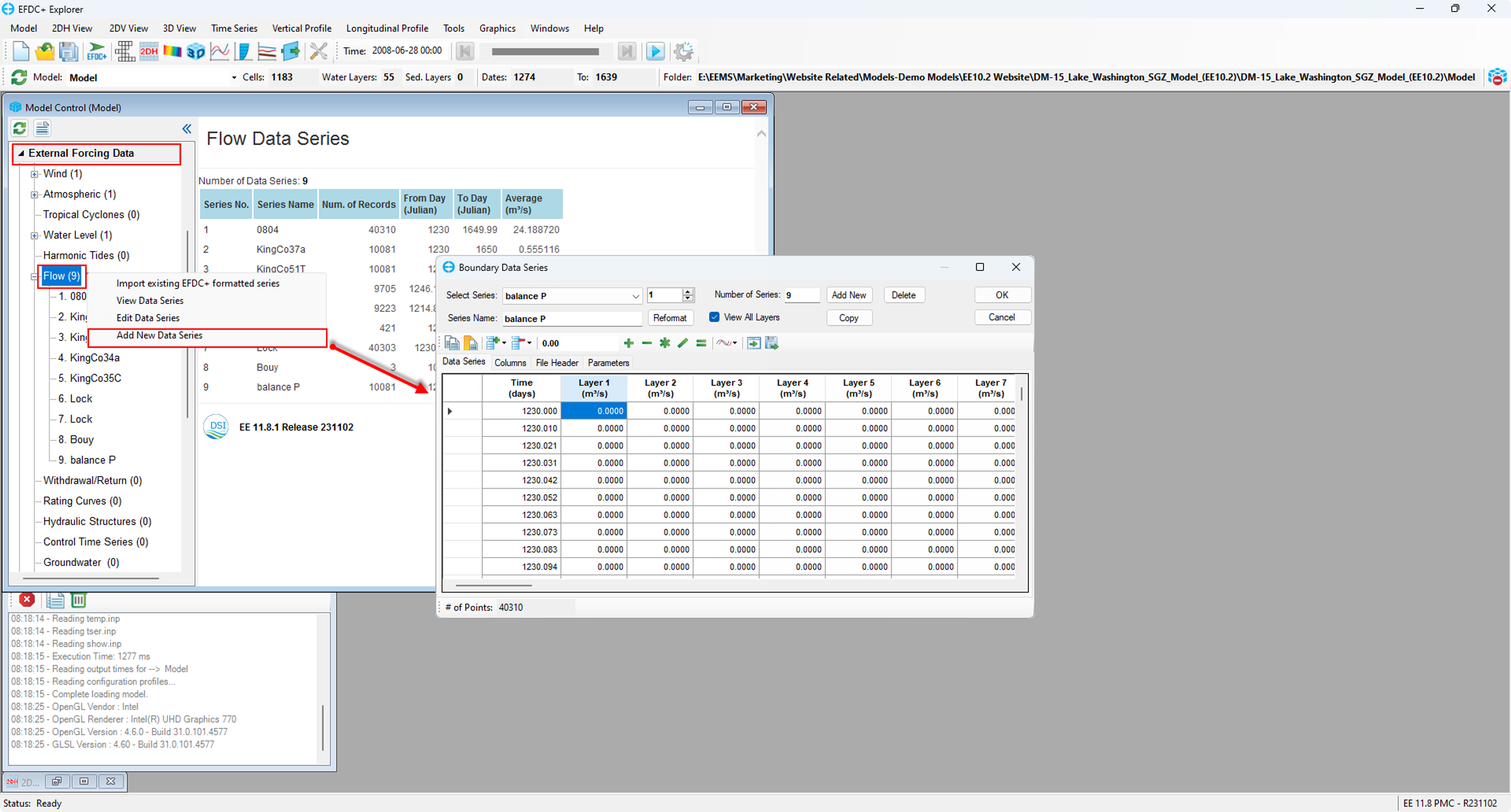
Before using the Reservoir Water Balance tool, it is necessary to have a time series for the water balance data, as shown in Figure 2. A new data series can be created, or an existing time series can be chosen. A new data series was created and named "Balance P" in this example.
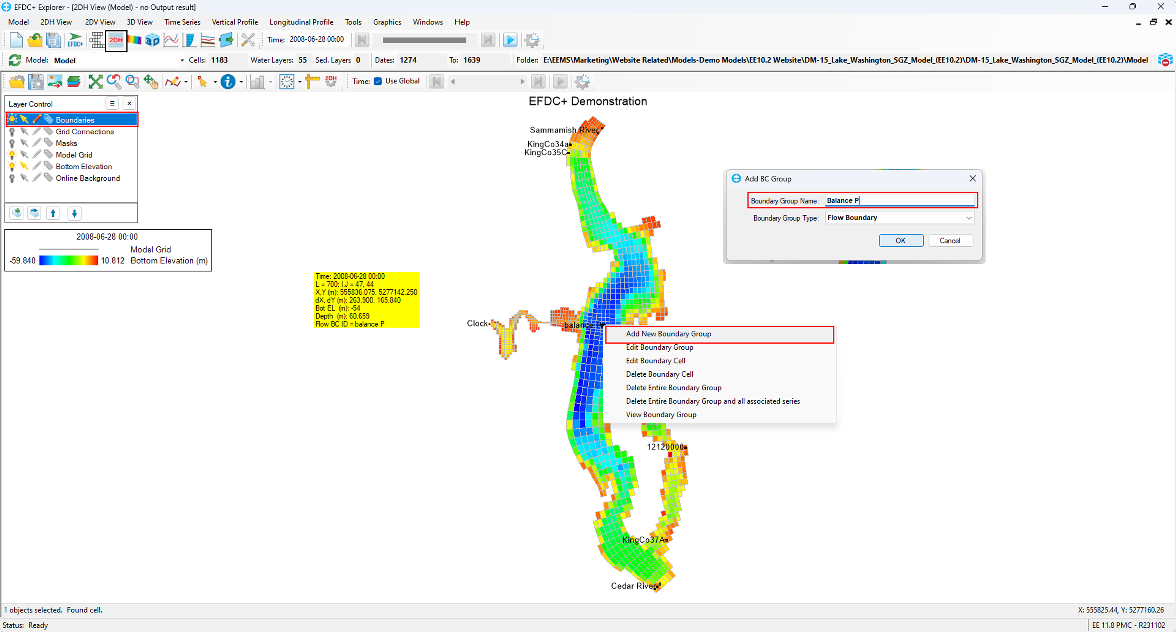
After this step, the location to input the balance time series must also be configured. The location in the model domain should be selected and set as a new boundary group, as shown in Figure 3. The flow series must then be assigned, as shown in Figure 4. When the model is next run, EE will use the Balance P time series to ensure that the water level stays at the level selected as the Control Water Level.
Figure 2. Time series for providing water balance.
Figure 3. The Location of the water balance time series
Figure 4. Flow boundary conditions


