...
Figure 12 Uniform Sediment Bed Generation.
Sediment cores are analyzed from the lab and recorded in the report. From the report the user can extract the information then fulfill in the form as shown in Figure 16, it includes the following information
- Put a name of core ( e.g Core1)
- Coordinates of the sediment core (X, Y, Z)
- Thickness of sediment layer, porosity and specific sediment gravity (SSG)
- Sieve size and percent passing of grain corresponding to each layer
- when it is done for each layer, the user click Add button to add the sediment layer.
- the user can update data for a layer by select the layer then change data its properties or delete the select layer
- Finally click OK button to finish for Core1. And the user can repeat by steps in Figure 15 and 16 for next sediment core.

Figure 16 Sediment Core Editing Form.
...

Figure 17 Save Cores Out (1).

Figure 18 Save Cores Out (2).
So now we have the sediment core data file ( e.g TraKhuc_Sed_Cores.dat) as shown in Figure 14. Now we can set initial condition for sediment as shown in Figure 13.
Set Up Boundary Condition for Sediment
- Go to Domain/Boundary Conditions
- Click E button to edit Cohesive and Non-Cohesive sediment (See Figure 19)Open 3D Coastal Sediment Model - Tra Khuc Estuary)
- Enter Number of Series = 1 then click F button
- Put a name of the series as River
- Enter timeseries data of cohesive and Non-cohesive in Data folder then Copy and paste on the form (See Figure 20 & 21)

...
Anchor #Figure 13 #Figure 13
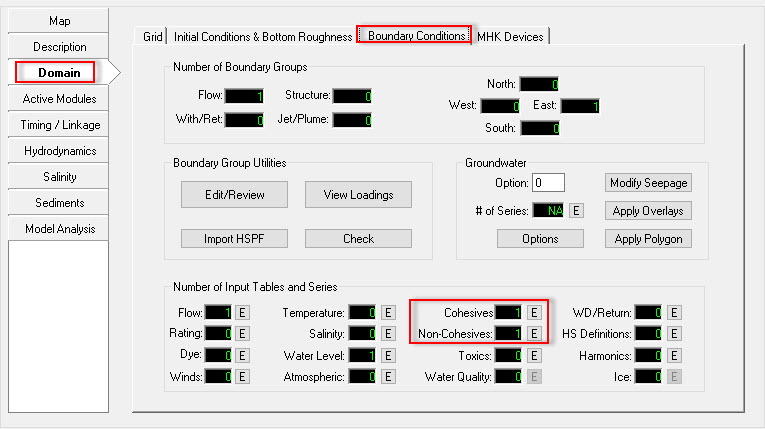
Figure 13 Boundary Sediment Settings.
Anchor #Figure 14 #Figure 14
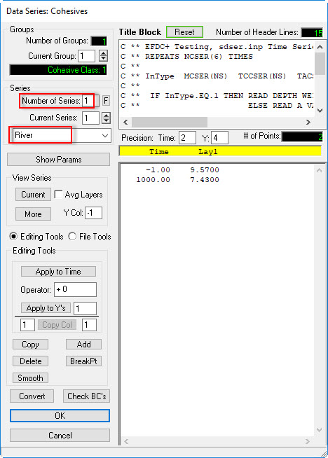
Figure 20 14 Cohesive Sediment Data Series.

Anchor #Figure 15 #Figure 15
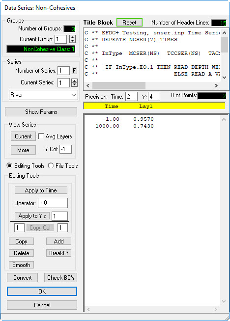
Figure 21 15 Non-Cohesive Sediment Data Series.
...
- Return EE main form then click Domain tab then Boundary Conditions sub-tab
- Click Edit/Review button (See Figure 22 3D Coastal Sediment Model - Tra Khuc Estuary)
- A form appears as shown in Figure 23, select US Flow (Upstream Flow), then click 3D Coastal Sediment Model - Tra Khuc Estuary, select "River", then double-click on that or click Edit button.
- In each type of sediment, click arrow then select corresponding sediment concentration table (See Figure 24 3D Coastal Sediment Model - Tra Khuc Estuary)
- Click OK button to finish
...
Anchor #Figure 16 #Figure 16
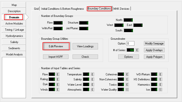
Figure 22 16 Edit Boundary Group.
Anchor #Figure 17 #Figure 17
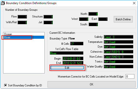
Figure 23 17 Boundary Condition Definition/Groups.
Anchor #Figure 18 #Figure 18
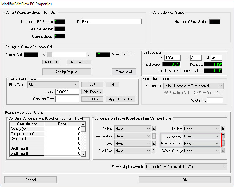
Figure 24 18 Modify/Edit Flow BC Properties.
...
Model Layers Setting
- Return EE main form then click Domain tab then Grid sub-tab
- Select Standard Sigma
- select Select number of water layers Water Layers = 5 then press Enter (See 3D Coastal Sediment Model - Tra Khuc Estuary)
Anchor #Figure 19 #Figure 19
| #Figure 19 | |
| #Figure 19 |
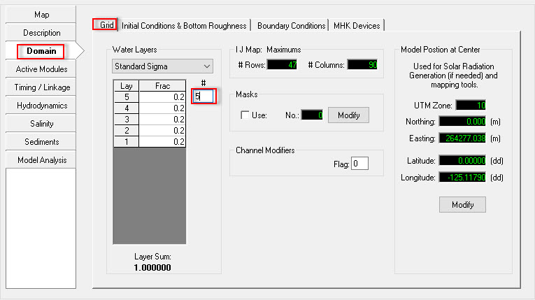
Figure 19 Set Water Layer of Model.
Save and Run Sediment Model
- Click Save Project button on the top of EE form to save the model again
- select EFDC executable file then clickClick Run EFDC button to run the model as shown in 3D Coastal Sediment Model - Tra Khuc Estuary
- 3D Coastal Sediment Model - Tra Khuc Estuary shows EFDC+ running window.
Anchor #Figure 20 #Figure 20
| #Figure 20 | |
| #Figure 20 |
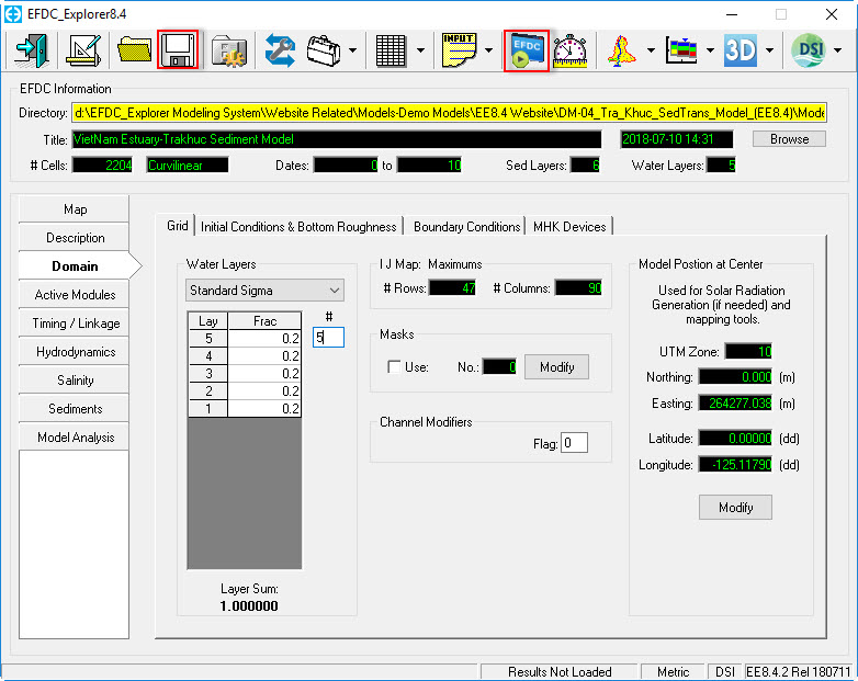
Figure 20 Save and Run Model.
Anchor #Figure 21 #Figure 21
| #Figure 21 | |
| #Figure 21 |

Figure 25 21 EFDC Sediment Model Running Window.
...