This external wave model option allows the user to import wave parameter fields from other common wave models. There are two options that can be selected from the drop-down list for the External Wave Model: SWAN Model and Other Model as shown in External Wave Model (EE10.3) and External Wave Model (EE10.3) Figure 1 and Figure 2.
| Anchor | ||||
|---|---|---|---|---|
|
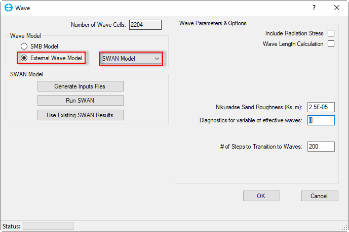
Figure 1 External Wave Model: SWAN Model.
...
When this option is selected, SWAN Model frame will be appeared appear with three options buttons including Generate Inputs Files, Run SWAN, Use Existing SWAN Results.
Generate Inputs Files: Click on this button to generate an input file for the SWAN model, the Create SWAN Input form pops up as shown in External Wave Model (EE10.3) Figure 3.
Generate SWAN Input frame: There are several optional check-boxes
Time Options frame: Define begin the beginning day, end day, and time step for the SWAN model, this time period should be in the range of the EFDC Model running time.
SWAN Settings: Click on that button to show the SWAN settings as shown in External Wave Model (EE10.3) Figure 4.
Boundary Conditions: If the Open Boundary Conditions check-box on the Generate SWAN Input frame is checked then the Boundary Conditions button is enableenabled, click on that button, form of SWAN Boundary Conditions appears as shown in External Wave Model (EE10.3) Figure 5. There are three options to set Forcing Type from existing boundary conditions of the model as No wave (External Wave Model (EE10.3))Figure 5), Constant (External Wave Model (EE10.3)Figure 6), Time-Varying (External Wave Model (EE10.3)Figure 7).
Export SWAN Input Directory: As default, the SWAN input file (swan_inp.swn) will be created and saved in the #analysis folder.
Anchor Figure 3 Figure 3

Figure 3 Create SWAN Model Input.
...
Figure 4 SWAN Input Parameters.
Anchor Figure 5 Figure 5

Figure 5 SWAN Boundary Conditions: No Wave.
Anchor Figure 6 Figure 6

Figure 6 SWAN Boundary Conditions: Constant.
Anchor Figure 7 Figure 7

Figure 7 SWAN Boundary Conditions: Time-Varying.
Run SWAN
After the SWAN input file has been created, the user now can run SWAN by clicking on Run SWAN button (External Wave Model (EE10.3)Figure 1), the SWAN Run Options form pops up as shown in External Wave Model (EE10.3) Figure 8.
SWAN Model Input: Click the Browse button to browse to the input file in the #analysis folder (swan_inp.swn)
SWAN Executable Path: Click the Browse button to browse to the executable file in SWAN folder of the EEMS installation folder.
Finally, click Run button in External Wave Model (EE10.3) Figure 8 to run SWAN model. External Wave Model (EE10.3) Figure 9 shows a running SWAN model window.
Anchor Figure 8 Figure 8

Figure 8 Run SWAN model.
Anchor Figure 9 Figure 9

Figure 9 SWAN model Running.
...
Click on that button, the Import SWAN Results form will appear as shown in External Wave Model (EE10.3) Figure 10. The user must define the type of SWAN model (Steady or Unsteady Wave) from the drop-down list. In the Get SWAN Results frame, the user select For Same Grid option (if the SWAN model and EFDC model have the same grid of model domain) or For Locations option ( if the SWAN model and EFDC model have a different grid of model domain) then browse to wave time file (wavetime.inp) and SWAN output file (swan_grp.out). In case the For Locations option is selected, the user needs to location file (swan_loc.inp) as shown External Wave Model (EE10.3). Finally Figure 11. Finally, click OK button to come back the Wave form. Note that the user needs to save the model again then the wave.inp file for the current model will be created.
...
When this option is selected, Wave Forcing from Other Wave Model frame will be appeared appear with two options buttons including Import from Existing WAVE. INP and Manual Assign Wave Parameters.
Import from Existing WAVE.INP: EE imports an available WAVE.INP file from another project into the current project (Note: two projects have exactly the same grids). When click clicking on this button, a message will be popped up as shown in External Wave Model (EE10.3). Figure 12. Click Yes button to proceed process. .
Anchor Figure 12 Figure 12
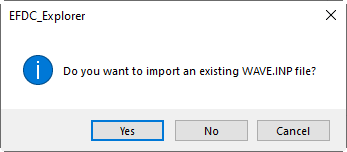
Figure 12 Message confirmation to import WAVE.INP
The Import WAVE.INP file form will appear, select the wave.inp then click Open button as shown in
...
Figure 13. After clicking Open button, it comes back to the Wave form. Note that the user needs to save the model again then the wave.inp file for the current model will be created.
Anchor Figure 12 Figure 12
12 Message confirmation to import WAVE.INPFigure Anchor Figure 13 Figure 13
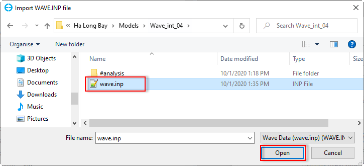
Figure 13 Import WAVE.INP file.
...
This option is not advised to be used due to the longer time required to prepare the input data. When this option is selected, an Interpolate Classed Data form will be appeared appear as shown in External Wave Model (EE10.3) Figure 14. In the Grid Options frame, select one of two options: All grid cells or Only grid cells inside polygon (when this option is selected, the Add File button in the Polygon Files frame below will be enableenabled). There are three options for Interpolation Options frame (Replacement, Max and Min values). In the Values to Set frame, select Constant if the user wants to set wave parameter parameters in grid cells with a constant values. Select From Scatter (XYZ) Data if the user have has a wave data file ( the file has three columns, the two first columns are coordinates, the third column is wave parameter value). When this option is selected, the Add File of Data File frame will be enableenabled). Next, select wave parameter from the drop-down list of the Parameters. Finally, Click Apply Defined Condition button then OK button. Note that the user needs to save the model again to create the wave.inp file for the current model.
Anchor Figure 14 Figure 14

Figure 14 Interpolate Classed Data form.
...