3D Coastal Sediment Model - Tra_Khuc Estuary
1 Introduction
This tutorial document will guide you how to setup a Coastal Sediment Model base on Tra_khuc example. So it is supposed that the hydrodynamic model of Tra_Khuc has been set ( Build a 3D Coastal Model). so that it adds the sediment transport to this model.
2 Generate a Sediment Transport Model
Open the Tra_Khuc Hydrodynamic Model ( See Figure 1)
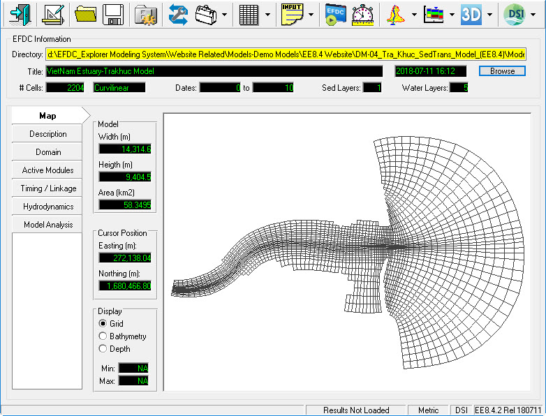
Figure 1 EE main form of Tra_Khuc Hydrodynamic Model.
Activate Sediment Modules
The user go to Active Modules tab, check on boxes to activate sediment ( See Figure 2), the Sediments tab will be added to the left-side tab.
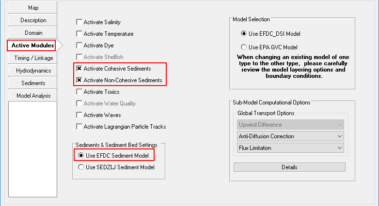 Figure 2 Activate Sediment Module.
Set Sediment Transport Parameters and Options
Click Sediments tab on the left-side tab then click Modify button (See Figure 3). A form of Sediments and Sediment Bed Properties appear, the user put the number of Sediment Bed Layers, Cohesives, and Non-cohesives ( See Figure 4).
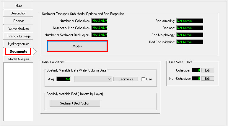
Figure 3 Editing Sediment Module.
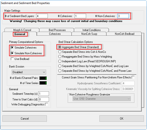
Figure 4 Sediment Transport – General.
Cohesives Tab
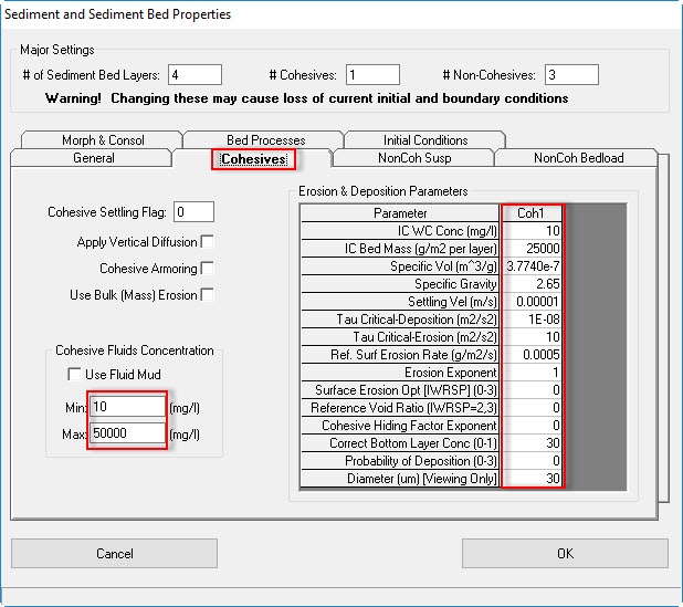
Figure 5 Sediment Transport – Cohesives.
Non-Cohesives Suspended Tab
The user put values of IC WC Conc, IC Bed Mass, Specific gravity, and Median Diameter then select Van Rijn option of Equilibrium Conc then click Set Parameters to initialize the sediment properties using the Van Rijn equations. (See Figure 6).
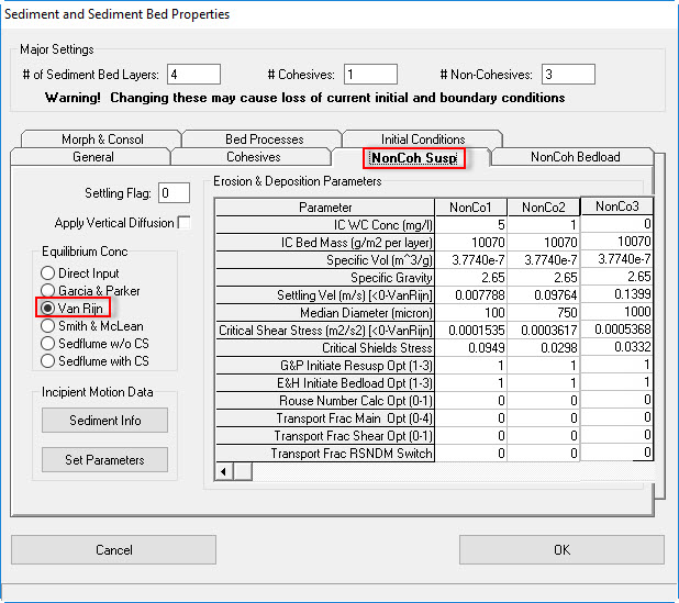
Figure 6 Sediment Transport – Non-Cohesives Suspended.
Non-Cohesives Bedload
Figure 7 shows the tab for the Non-Cohesives Bedload. Pressing the Initialize Constants button will bring up a dialog box asking the user to select the bedload approach to use ( See Figure 8 ). EFDC_Explorer sets the bed load transport constants to standard literature values for the computational approach selected.
Put 1 then click OK button. Click Set All button to set all non-cohesive bedload to the current class.
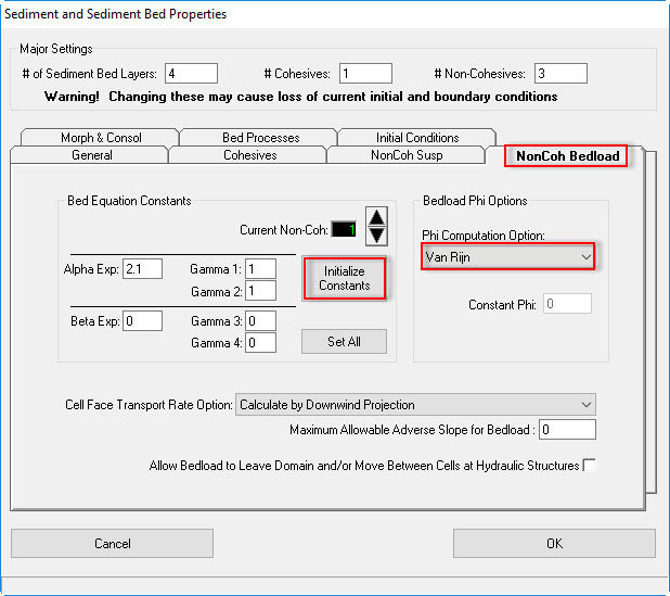
Figure 7 Sediment Transport – Non-Cohesives Bedload.
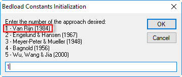
Figure 8 Bedload Constants Initialization.
Morphology and Consolidation Tab
Figure 9 shows the tab for the Morphology & Consolidation of the sediment properties option. In this tab the user may specify various bed consolidation and bed morphology settings.
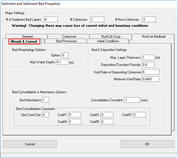
Figure 9 Sediment Transport – Morphology and Consolidation.
Bed Processes
Figure 10 shows the tab for the Bed Processes.

Figure 10 Sediment Transport – Bed Processes.
Initial Conditions Tab
There are several ways to build sediment beds in EFDC_Explorer. The simplest option is to create a uniform bed as shown in Figure 11. Other option, using a sediment cores with grainsize which is described in Sediment Bed Core Initialization.
Figure 11 shows the sediment parameters form with the Initial Conditions tab selected.
- Select Spatially Varying Bed Conditions; Specify Mass Fraction
- Click Create Uniform Bed button, a form of Inorganic Sediment Bed Constructor appears, enter values for uniform cohesives and Non-cohesives as shown in Figure 12
- Then click Create Sediment Bed button
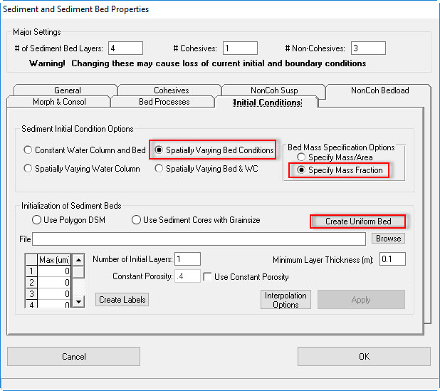
Figure 11 Sediment Transport – Initial Conditions.
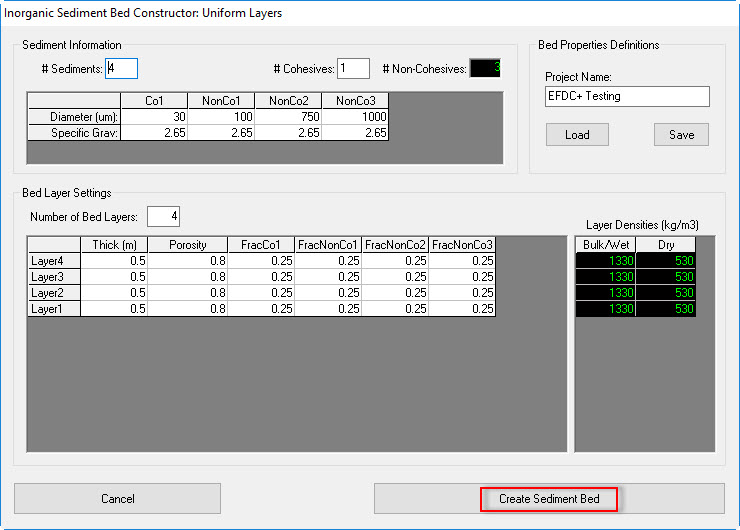
Figure 12 Uniform Sediment Bed Generation.
Set Up Boundary Condition for Sediment
- Go to Domain/Boundary Conditions
- Click E button to edit Cohesive and Non-Cohesive sediment (See Figure 13)
- Enter Number of Series = 1 then click F button
- Put a name of the series as River
- Enter timeseries data of cohesive and Non-cohesive on the form (See Figure 14 and Figure 15 )
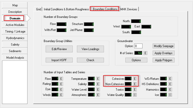
Figure 13 Boundary Sediment Settings.
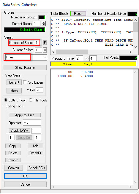
Figure 14 Cohesive Sediment Data Series.
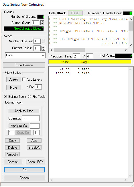
Figure 15 Non-Cohesive Sediment Data Series.
Assigning the sediment concentration BC
- Return EE main form then click Domain tab then Boundary Conditions sub-tab
- Click Edit/Review button (See Figure 16)
- A form appears as shown in Figure 17, select "River", then double-click on that or click Edit button.
- In each type of sediment, click arrow then select corresponding sediment concentration table (See Figure 18)
- Click OK button to finish
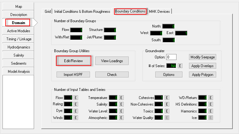
Figure 16 Edit Boundary Group.
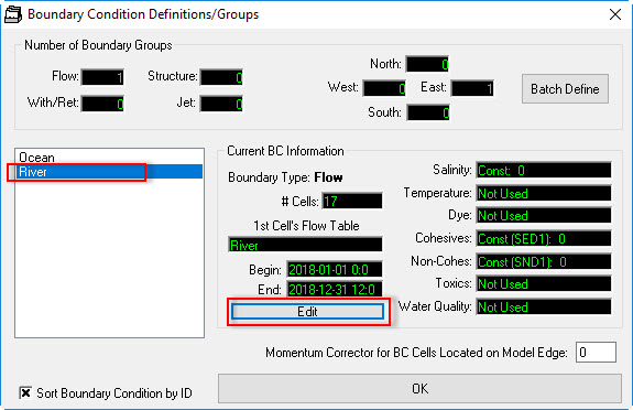
Figure 17 Boundary Condition Definition/Groups.
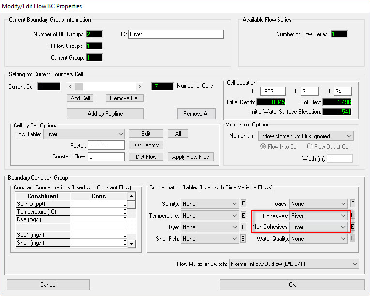
Figure 18 Modify/Edit Flow BC Properties.
Model Layers Setting
- Return EE main form then click Domain tab then Grid sub-tab
- Select Standard Sigma
- Select number of Water Layers = 5 then press Enter (See Figure 19)
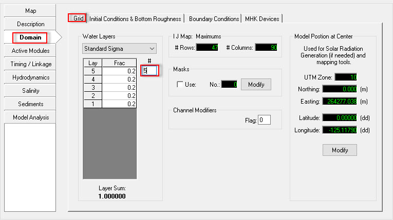
Figure 19 Set Water Layer of Model.
Save and Run Sediment Model
- Click Save Project button on the top of EE form to save the model again
- Click Run EFDC button to run the model as shown in Figure 20
- Figure 21 shows EFDC+ running window.
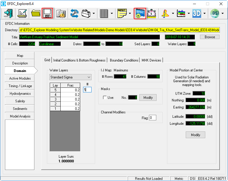
Figure 20 Save and Run Model.
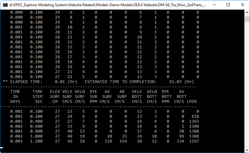
Figure 21 EFDC Sediment Model Running Window.