West Lake Toxics Model (Level 2 Step-by-Step Guidance)
1 Introduction
The toxics model is built based on an existing sediment transport model of West Lake. This example model can be downloaded from the EEMS website . The steps required to build a sediment model are introduced in Tra Khuc Coastal Sediment Model.
This tutorial document will guide you on how to set up a toxics model based on the West Lake example. It is assumed that the sediment transport model of West Lake has been set and that toxics will be added to this model.
2 Generate a Toxics Model
Open the West Lake Sediment Transport Model ( See Figure 1)
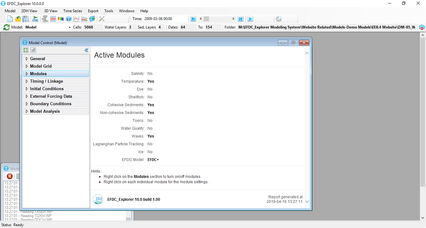 Figure 1 EE main form of West Lake Sediment Model.
2.1 Activate Toxics Modules
RMC on Modules in the Model Control form, check on the box to activate toxics (Figure 2), the Toxics menu item will be added to Modules.
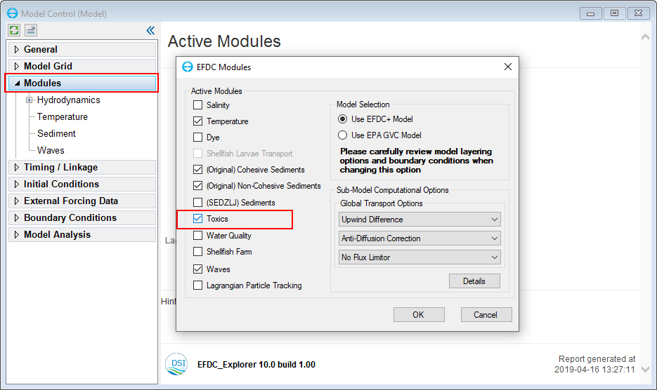
Figure 2. Activate toxics module.
2.2 Set Toxics Options
RMC on Toxics tab under Modules on then select Settings (Figure 3).
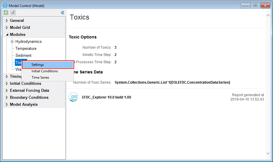
Figure 3. Editing toxics module (1).
The Toxics and Sediment Bed Toxics Properties form is displayed to set the toxics parameters. Input the number of toxics = 3 then click the OK button (Figure 4).
In Global Options (All Toxics) tab, set parameters as shown in Figure 4.
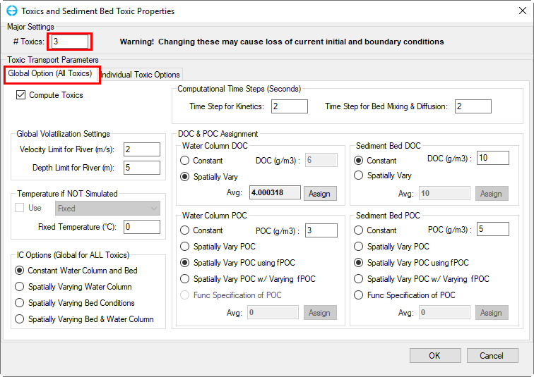
Figure 4 Editing toxics module (2).
In the Individual Toxic Options tab, three toxic transport parameters will be created from Toxic 1 to 3 and each toxic parameter will have a corresponding name in Toxics box. The user can put a desired name for each toxic parameter ( See Figure 5)
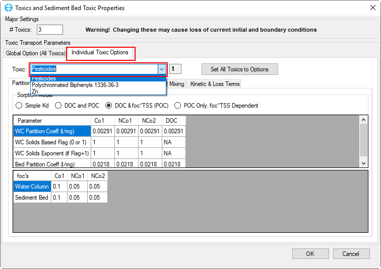
Figure 5. Editing toxics module (3).
Partition Coefficients Tab
Select Toxic 1, and enter the name as "Pesticides" as toxic name. Select DOC & foc*TSS (POC) option. Enter values for two table forms as shown in Figure 6.
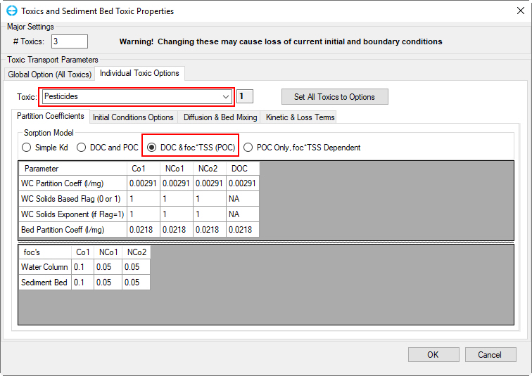
Figure 6. Toxic No. 1 sorption model and partition coefficients.
Do the same steps for to Toxic 2 and Toxic 3 as shown in Figures 7 and 8.
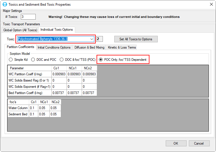
Figure 7. Toxic No. 2 sorption model and partition coefficients.
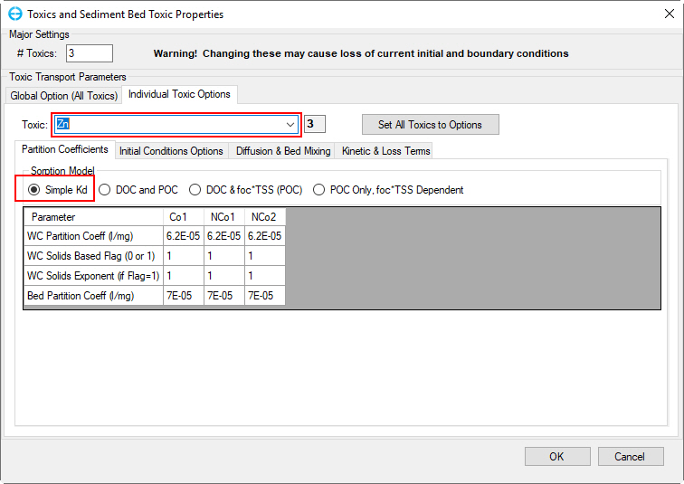
Figure 8. Toxic No. 3 sorption model and partition coefficients.
Initial Conditions Options Tab
The Initial Conditions Options of the toxics properties option is shown in Figure 9. In this tab the user may specify toxic water column IC and Toxic bed IC. Input the properties for three toxics as shown in Figure 9.
- Select Toxic 1
- Select Constant Water Column & Bed
- Select Mass Tox/Sed (mg/kg)
- Input values 0.2 for Bed Toxic IC and 0.3 for Water Column Constant IC
In Toxic Transport Parameters
- Select Toxic 2. Input values 0.05 for Bed Toxic IC and 0.1 for Water Column Constant IC (Figure 10)
- Select Toxic 3. Input values 0.025 for Bed Toxic IC and 0.05 for Water Column Constant IC (Figure 11)
Finally, click OK button to complete.
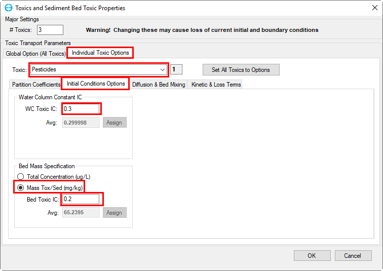
Figure 9. Toxic No. 1 IC settings.
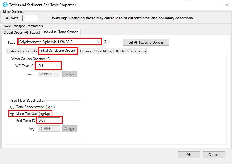
Figure 10. Toxic No. 2 IC settings.
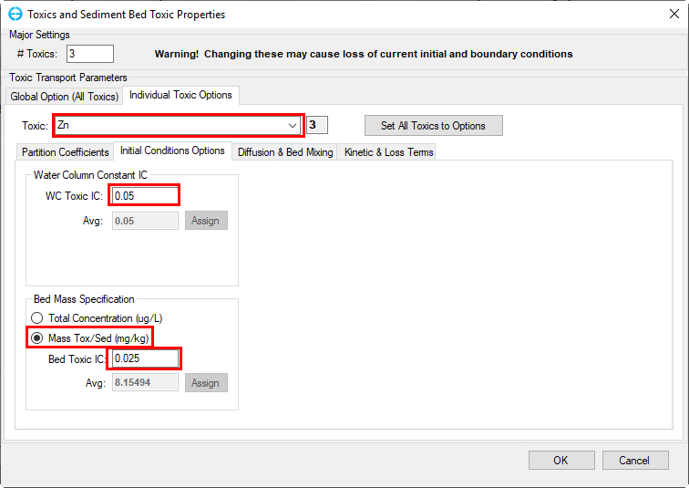
Figure 11. Toxic No. 3 IC settings.
Diffusion & Bed Mixing Tab
The Diffusion & Bed Mixing tab is shown in Figure 12 . The user should set the porewater diffusion rates and bed surface particle mixing parameters of the toxic properties. Enter values for these parameters as in Figure 12 below.
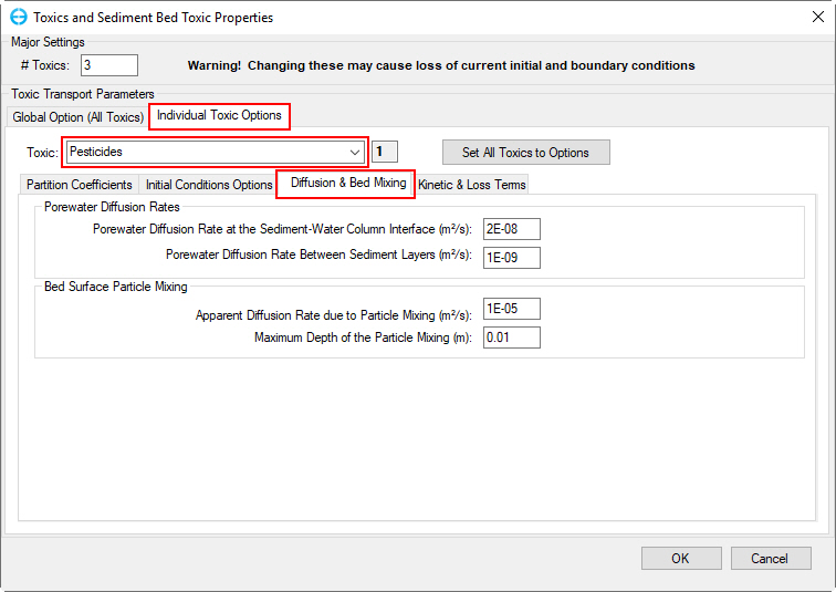
Figure 12. Toxic No. 1 Diffusion & Bed Mixing settings.
Do the same steps for Toxic 2 and Toxic 3 as shown Figures 13 and 14 below.
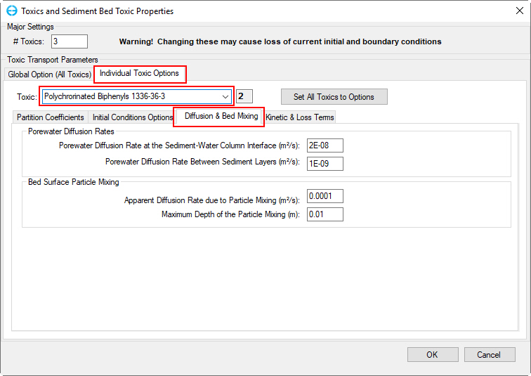 Figure 13. Toxic No. 2 Diffusion & Bed Mixing settings.
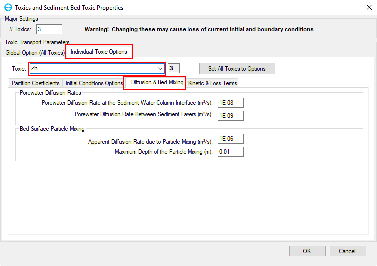
Figure 14. Toxic No. 3 Diffusion & Bed Mixing settings.
Kinetic & Loss Terms Tab
The Kinetic & Loss Term tab is shown in Figure 15. Enter values for kinetic and loss terms as shown in Figure 15.
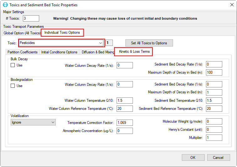 Figure 15. Toxics Kinetic & Loss Terms setting.
Enter similar values for Toxic 2 and 3 as those for Toxic 1.
2.3 Boundary Conditions for Toxics
2.3.1 Set Time Series
In Model Control form, select External Forcing Data tab, RMC on Toxic Data, select Add a New Data Series to add toxic data series (Figure 16)
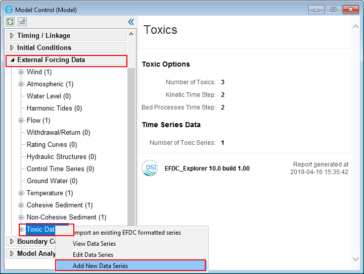 Figure 16. Toxics data series form.
- Input "1" into the # box or select Add new button to add a data series (Figure 17)
- Fill time series data of for toxic class 1 as shown in Figure 17.
- Click on drop-down menu to select toxic class 2 and 3 to input the time series data in the same was as for toxic class 1 (Figure 17).
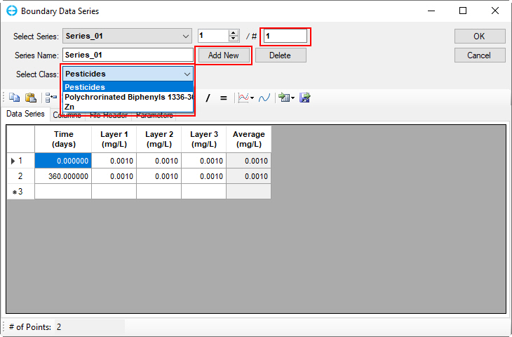 Figure 17. Toxics class 1 Boundary Data Series form.
- Fill in time-series data series for toxic class 2 and 3 as shown in Figure 18 and Figure 19
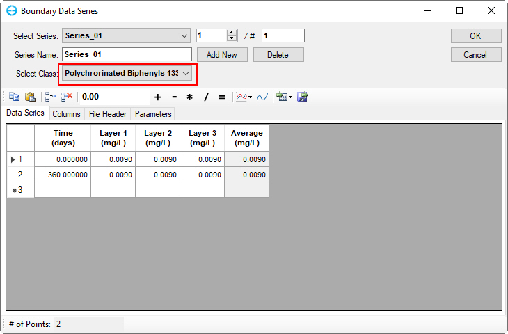 Figure 18. Toxics class 2 Boundary Data Series form.
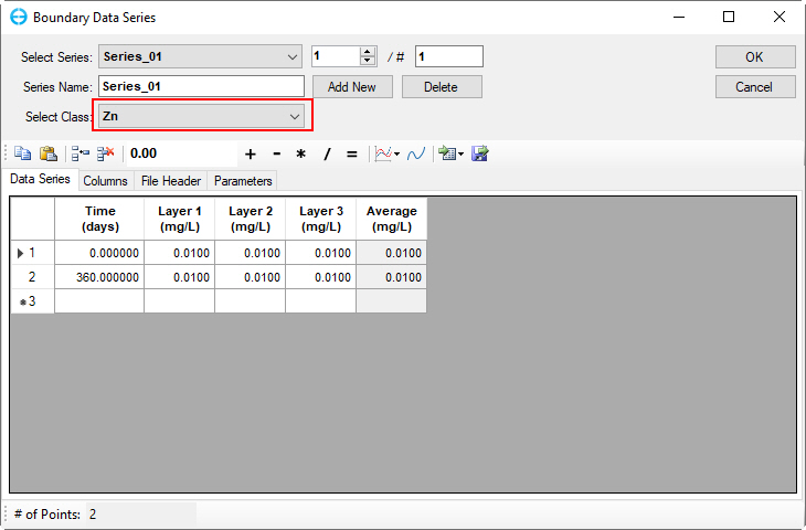
Figure 19. Toxics class 3 Boundary Data Series form.
- Click OK to finish editing the toxics time series data.
2.3.2 Assigning Boundary Condition
In order to assign the boundary, the following steps should be taken;
- From Model Control form, select Boundary Conditions, expand Flow boundary group and select "Cong Do" boundary group (Figure 20).
- RMC on "Cong Do" then select Edit Boundary Group (Figure 21).
- The Flow Boundary Conditions form appears (Figure 22). Click the drop-down arrow to select Series_01 for Toxics then click OK button (Figure 22).
- Repeat from steps 1-3 for the other BCs remaining (e.g Giay TB, Ly Tu Trong etc.)
- From Model Control form, select Model Grid tab, RMC on Layers to open the Model Grid form to set number of water layer (Figure 23)
- Enter number of water layer as 3 in # Layers box then click OK button (Figure 23).
- Save model again then click Run EFDC button.
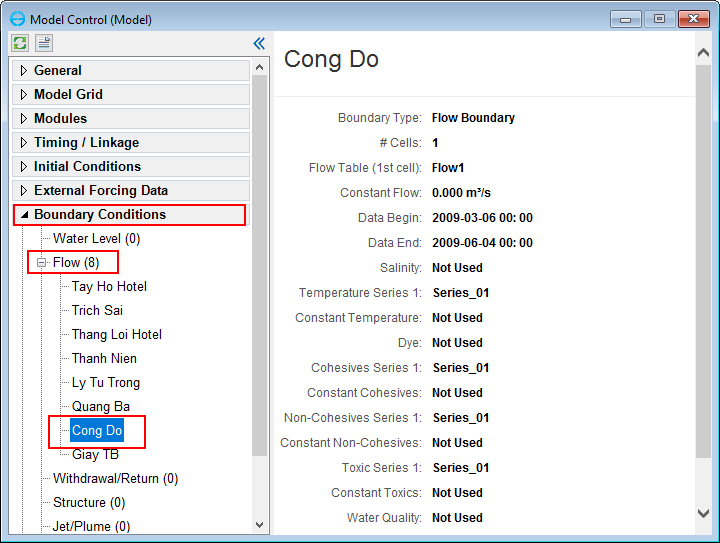
Figure 20. Boundary Groups form (1).
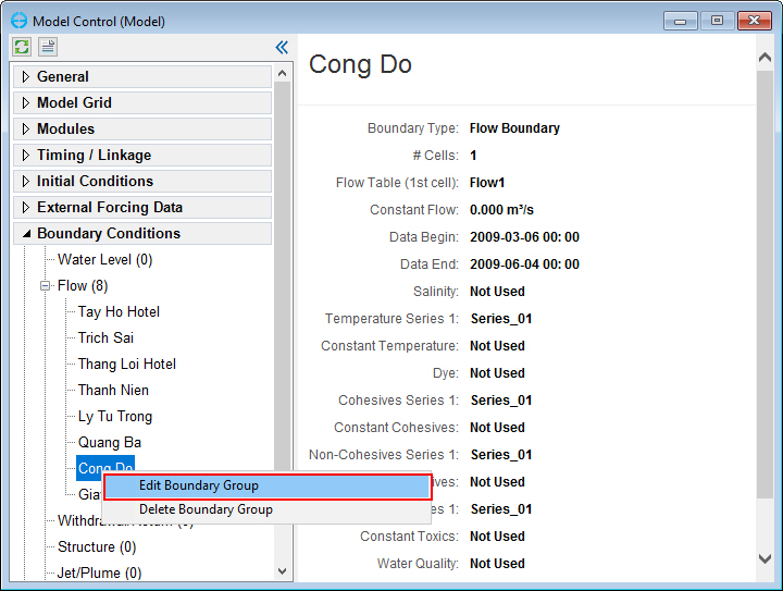
Figure 21. Edit Boundary Groups option.
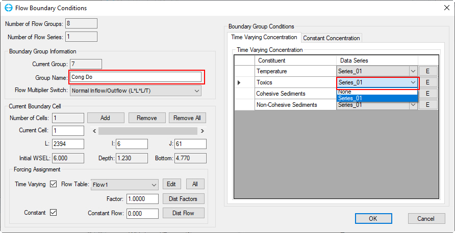
Figure 22. Assign toxics timeseries for "Cong Do".
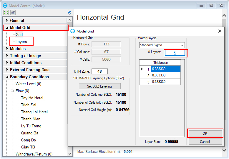
Figure 23. Set number of vertical layers for the model.
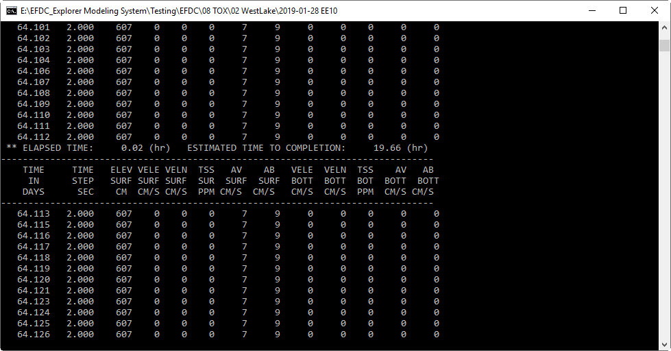
Figure 24. Run EFDC+ Window
End.