Polygon/Polyline Information Tool
The tool for editing the information related to each polyline is shown in Figure 1 and various options described in more detail below.
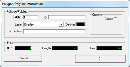
Figure 1 Polygon/polyline information window.
In the Polygon/Polyline sub frame the user can cycle through the current polygons and polylines using the arrow buttons. As the user cycles, the polygon number and ID are displayed on the right. The user can change a polyline ID by clicking in the text box and typing the desired ID.
The Layer drop down menu shows what layer the current polygon is on. Defined simply shows how many available layers are in the Layer Control. Description allows the user to describe the polygon/polyline.
The Options frame allows the user to close the polylines, thus creating polygons. When this box is checked the "Area" display box will show the area in meters within the current polygon.
The Stats window displays the polygon/polyline statistics. For the currently selected line it shows the number of points, the length, and the area. However, the area is only shown when the line is a polygon.
In the Edit RK/RM Options Window the user can LMC on Symbol and Font buttons to change the symbol and font as shown in Figure 2 and Figure 3 respectively. In addition, the user can modify the starting RK and Delta (m) and unit for display on the polyline. Figure 4 shows RK labels displayed on the polyline.
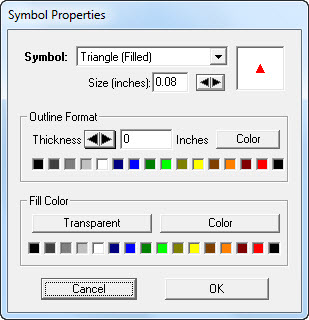
Figure 2 Symbol properties settings.
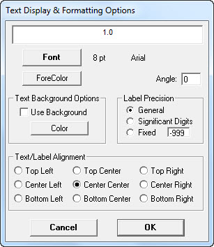
Figure 3 Font properties settings.
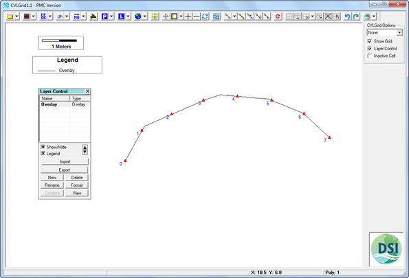
Figure 4 RK labels displaying on a polyline.
The Copy to Another Layer feature allows users to move spline to overlays and vice-versa.
When there are from two layers types (both Overlay and Spline) in the Layer Control, the Copy to Another Layer function is enabled as shown in Figure 5. The user may then define a destination layer for copying the polygon/polyline to as shown in Figure 6. For an Overlay type, it can be copied to another Overlay or a Spline layer. Then it will have properties of the layer it is copied to.
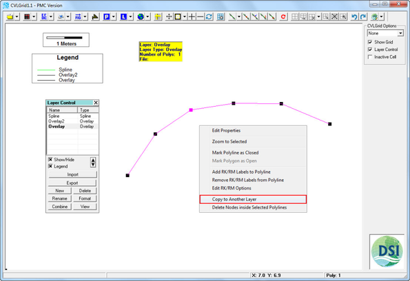
Figure 5 Copy to another layer function.
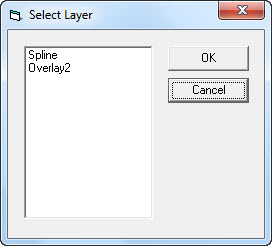
Figure 6 Destination layer selection.
The Delete Nodes inside Selected Polylines function is enabled when there is a Grid layer in Layer Control. It allows the user to delete all the grid nodes inside the polyline.