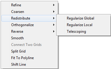
The Redistribute Grid tool has three options: Regularize Global creates even spacing between cell's nodes for entire grid domain. Regularize Local creates even spacing between cell's nodes in either the I or the J direction of grid domain by selecting two nodes on a grid line. Telescoping creates increasing or decreasing spacing to a side of the grid block specified by three cell nodes and depends on a distance factor value in the Telescoping settings.
...
| Anchor |
|---|
...
|
...
1 Sub-options for redistribute a grid.
...
...
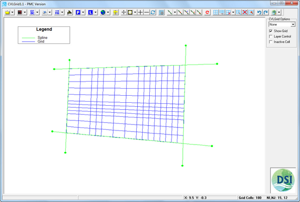
4 demonstrates how Regularize Global and Regularize Local affect the grid.
...
| Anchor |
|---|
...
|
...

| Anchor |
|---|
...
|
...
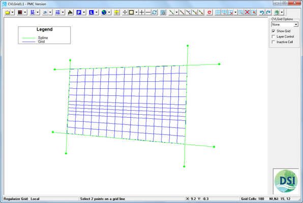
3 Grid after applying Regularize Global.
...
| Anchor |
|---|
...
|
When the user selects Telescoping, the mouse cursor transforms from an arrow to a cross hair. Three nodes to be selected in the Telescoping option. The user needs to first select two nodes on same grid line which are perpendicular to the direction in which the grid will be telescoped or stretched. The user should then select a third node on grid domain which the end point to which the telescoping will be applied. These three nodes define a grid block which the telescoping will be apply too.
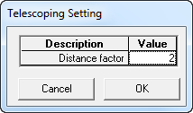
After selecting the third node, a window for the Telescoping Setting appears to allow the user to enter the value of a distance factor. The default value of the distance factor is two and the distance factor must be a whole number greater than 1. After entering the telescoping factor click OK. The distance between the first two nodes in the grid block increases gradually towards the third node specified.
...
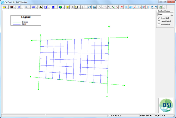
5 shows the grid before applying telescoping; Figure 6
...
is an example of selecting three grid nodes for telescoping. Figure
...
7 shows the telescoping setting
...
and Figure
...
8 shows the grid after applying telescoping
...
...
| Anchor |
|---|
...
|
...

| Anchor |
|---|
...
|
...
| Anchor |
|---|
...
|
...

| Anchor |
|---|
...
|