1. Introduction
...
- On the main form of EE click to the 2D Planview icon

- Choose Boundary C’s in the Viewing Opt’s ( Figure 14).
- Check Enable Edit and Show Grid (Figure 14).
- Right-Mouse-Click on the inflow location cell/ choose New (Figure 15).
- Enter the boundary group ID: Inflow group (Figure 16).
- Select boundary types. It is dependent on your current boundary type to choose the suitable boundary type. In this case, we have 1 flow boundary so we choose number 1 (Figure 17).
- Select the flow table associated with this inflow boundary time series from the dropdown list (Figure 18).
- Click OK to complete.
- The boundary cells might have multiple cells. In order to assign the next cell as inflow cell, you need to come back to step 4 and Right-mouse Click to that cell and choose to Add to Adjacent. The inflow is now divided into the number of assigned cells (Figure 19 and Figure 20).
...
Figure 32 Model Run Timing.
7. Running EFDC
This section runs the EFDC model and includes the following steps:
1. Select the Setting icon ![]() on the main EE form to browse to the EFDC Executable file (Figure 33). By default this file is in the installation folder C:\Program Files(x86)\DSI\EFDC_ExplorerXX
on the main EE form to browse to the EFDC Executable file (Figure 33). By default this file is in the installation folder C:\Program Files(x86)\DSI\EFDC_ExplorerXX
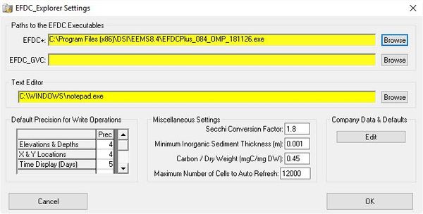
Figure 33 Browse to the EFDC executable file.
2. Select the Run EFDC icon ![]() on the main form and click the Run EFDC+ button to run the model.
on the main form and click the Run EFDC+ button to run the model.
3. If all settings are correct, the model will start running and users will see the MS-DOS Window appear showing the model results as shown in Figure 34
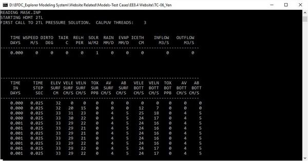
Figure 34 Run EFDC run window.
...