...
...
...
...
...
...
...
...
...
...
The Sediment Transport Module can be activated by right mouse click (RMC) on Modules in the Model Control (see Figure 1).
EFDC_Explorer10.0 provides three options for setting up the sediment bed model :
- Cohesive sediments
- Non-cohesive sediments
- SEDZLJ sediments
Various input parameters of Cohesive/Non-cohesive Sediment are described in the next section.
...

Figure 1 Activate sediment modules.
2. Setting Sediment Modules
1.RMC on the Sediment and select Settings to see the dialogue box of Sediment Bed Properties.

Figure 2 Settings of sediment module.
...
...
- Click the Modules tab and check on one of boxes (Original) Cohesive Sediments, (Original) Non-Cohesive Sediments, SEDZLJ Sediments then click OK button. (see Figure 1).
- After that Sediment tab will be added to Modules Tab. RMC on the Sediment Tab then select Settings. The Sediment and Sediment Bed Properties Settings appears.
- Define the number of sediment bed layers, cohesive and non-cohesive sediments as shown in
...
- Major Settings of EFDC Sediment Model (it is important do this first to avoid losing data).
- Set the options in the
...
- General
...
- tab for the
...
- Primary Computational Options
...
- and the
...
- Bed Shear Calculation Options
...
- .
...

...
...
- In
...
- Cohesive
...
- tab
...
- the user should enter the appropriate values for the relative parameters as well as defining the minimum and maximum values of
...
- Cohesive Fluids Concentration
...

Figure 4 Sediment bed model: Cohesives Tab.
...
- as shown in Figure 2.
- In the Non-Cohesive Suspended
...
- tab the user should define the
...
- Equilibrium Concentration Option
...
- and enter the appropriate values for the relative parameters and non-cohesive layers
...
- .
...
- In the
...
- Non-cohesive Bed
...
- tab the user should click on
...
- Initialize Constants
...
- button and enter the number for the approaches desired e.g. enter "1" for the Van Rijn approach
...

...
- .
...
- In
...
- the Morphology & Consolidation
...
- tab the user should select the Bed Morphology Options: 0-No Bed Change, 1-Allow Bed Changes. The user should also set the Max Layer Thickness and Constant Porosity to be the same values as in the input sediment file
...

Figure 7 Sediment bed model: Morphology & Consolidation Tab.
...
- (refer to Appendix B - Data Formats for the DSM format of the file).
- In the Initial Conditions tab: select the Sediment Initial Condition Options
...
- .
...
- Then
...
- click Assign Bed IC
...
- button, there are 2 options to initialize bed layers: Uniform bed and use initial data file.
- Initialize the sediment bed from file, browse for the input sediment file
...
- Check
...
- Use sediment cores with grain size
...
...
- Define the maximum grain size for each size class relatively to cohesive and non-cohesive layers as displayed in the in the red frame in Figure
...
- 3.
If the required information has been entered then the Apply is button is visible. After clicking on Apply, the sediment bed will be initialized.
Anchor Figure 1 Figure 1
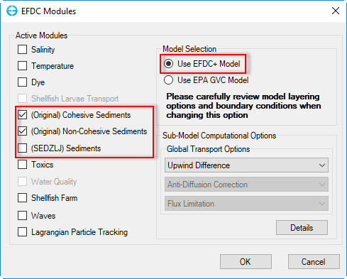
Figure 1 Activate sediment modules.
8Anchor Figure
82 Figure 2

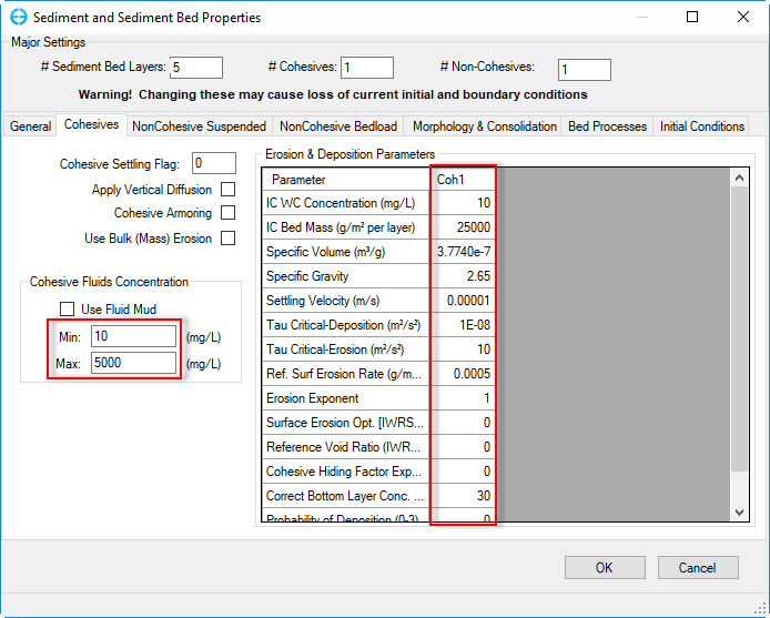
Figure 8 Sediment bed model: Initial Conditions Tab2 Sediment Bed Model: Cohesives Tab.
Anchor Figure 3 Figure 3

Figure 3 Initialization of Sediment Beds.