1 Introduction
...
- In the Model Control form, RMC on Modules to open the EFDC Modules window.
- In EFDC Modules, check the boxes (Original) Cohesive Sediments and (Original) Non-Cohesive Sediments to activate sediment then click OK. The Sediments item will be added under Modules.
| Anchor | ||||
|---|---|---|---|---|
|
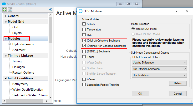
Figure 2. Activate the sediment module.
...
- Right Mouse Click on Sediments tab under Modules then click Settings to open Sediments and Sediment Bed Properties window (Figure 3).
- In the General tab the user inputs the number of Sediment Bed Layers, Cohesives, and Non-cohesives (Figure 4)
| Anchor | ||||
|---|---|---|---|---|
|

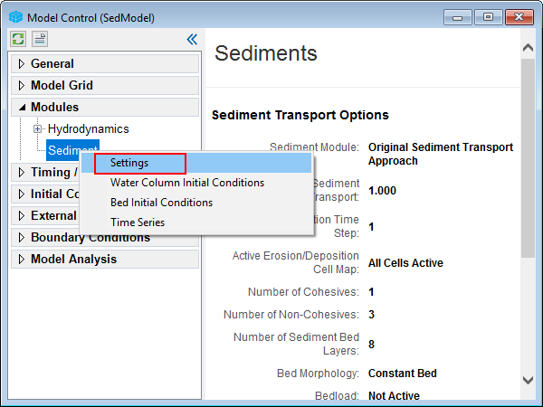
Figure 3. Editing the sediment module.
...
The user ahould input values for IC WC Conc, IC Bed Mass, Specific Gravity, and Median Diameter as shown in Figure 6. In the Equilibrium Conc, check on Van Rijin then click Set Parameters to initialize the sediment properties using the Van Rijn equations.
...
Figure 7. Sediment Transport – Non-Cohesives Bedload tab.
Anchor #Figure 8 #Figure 8

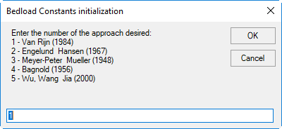
Figure 8 Bedload Constants Initialization form.
...
1. From Model Control form, under External Forcing Data, RMC on Cohesives Sediment and select Add New Data Series (See Figure 14) then the Boundary Data Series form appears.
2. In the new Boundary Data Series form, click on Add New
3. Input the name of the series as "River" in Series Name then press Enter key from keyboard.
4. Enter time-series data of cohesive sediment from Figure 14 then click OK button to finish.
Anchor #Figure 14 #Figure 14

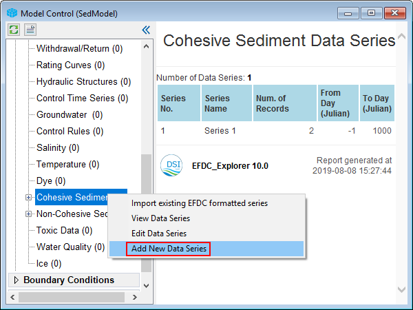
Figure 14. Cohesive Sediment: add new data series.
Anchor #Figure 15 #Figure 15
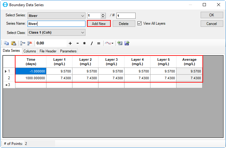
Figure 15. Cohesive sediment data series.
5. Do the same Add data time series for Non-Cohesives Sediment with data from Figure 15 as shown in Figure 16 and Figure 17 (remember to put in data for 3 non-cohesive classes)
Anchor #Figure 1516 #Figure 15

Figure 1516
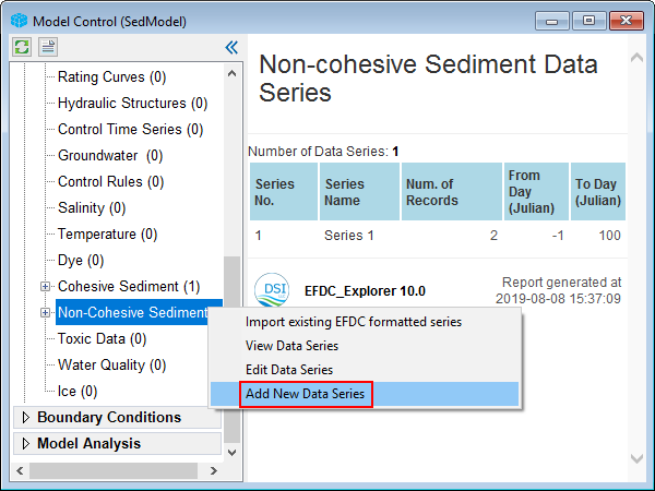
Figure 16. Non-Cohesive Sediment: add new data series.
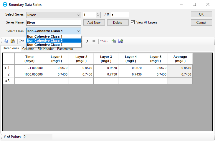
Figure 17. Non-cohesive sediment data series.
...
1. Return to the Model Control form, RMC on the River under Flow of the Boundary Conditions tab then select Edit Boundary Group (Figure 1618)
Anchor #Figure 1618 #Figure 1618
...
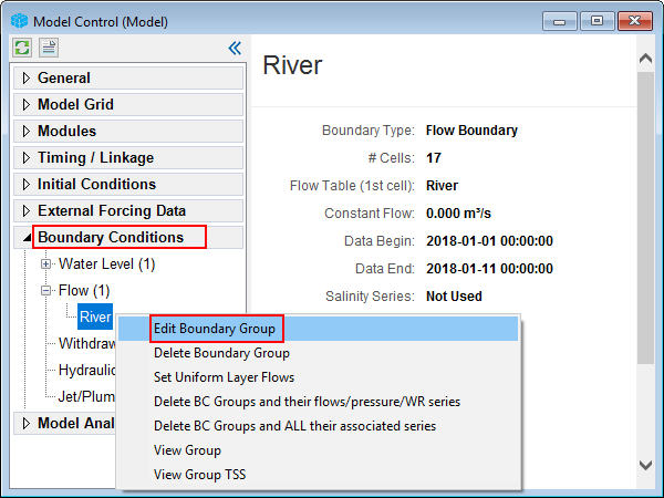
Figure 16 18 Edit Boundary ConditionsGroup conditions.
2. The Boundary Condition Definition/Groups form Flow Boundary Conditions form appears as shown in Figure 1719, in Boundary Group Conditions, from drop-down list, select data series with named as "River" , then double-click on that or Right Mouse Click and select Editfor Cohesive Sediment and Non-cohesive Sediments , then OK button.
| Anchor | ||||
|---|---|---|---|---|
|

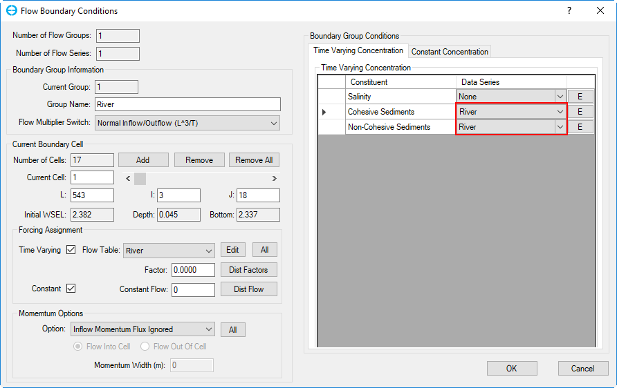
Figure 1719. Boundary Boundary Condition Definition/Groups form.
3. For each type of sediment, click the arrow then select corresponding sediment concentration table (Figure 18)
...
.
...
4. Click the OK button to finish
Anchor

Figure 18. Modify/Edit Flow BC Properties.
3 Save and Run Sediment Model
- Click the Save Project button
 on the top of EE form to save the model again as shown in Figure 20.
 - Click the Run EFDC
 button to run the model , the EFDC+ Run Options frame appears as shown in Figure 1921. On this form, the user can set the number of threads, output interval then browse to the EFDC+ executable file. Then click Run EFDC+ button to run model.
 - The EFDC+ run window is shown in Figure 2022.
Anchor #Figure
| #Figure |
...
20 #Figure
| 20 | |
| #Figure |
...
20
| 20 |

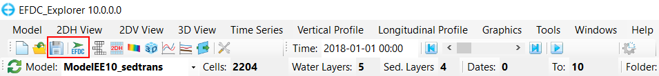
Figure 1920. Save and run model.
Anchor #Figure
| #Figure |
...
21 #Figure
| 21 | |
| #Figure |
...
21
| 21 |
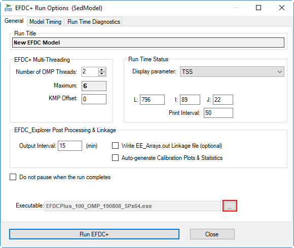
Figure 21. EFDC+ Run Options.
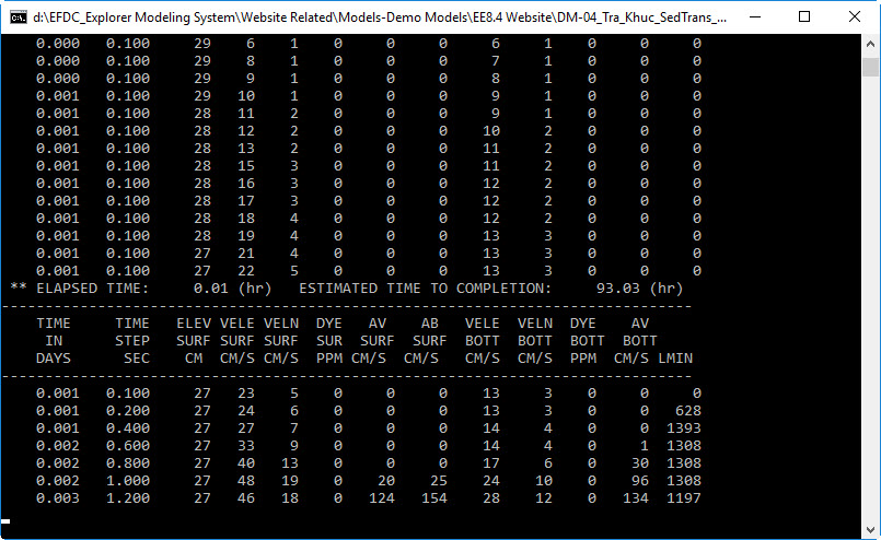
Figure 2022. EFDC+ run window.