...
First two data columns above provide the sequence of all horizontal (I, J) grid cells that are required for correct setup of the EFDC.WSP control file. The user can prepare a correctly formatted EFDC.WSP file by importing the DXDY.INP file into Excel to get the correct sequence of I and J grid cells. Insert a third column after the imported I, J records from the DXDY.INP and insert the assignment of ABMAX value (as m**2/sec) desired for each grid cell.
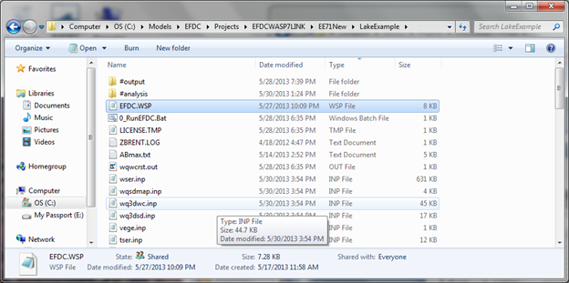
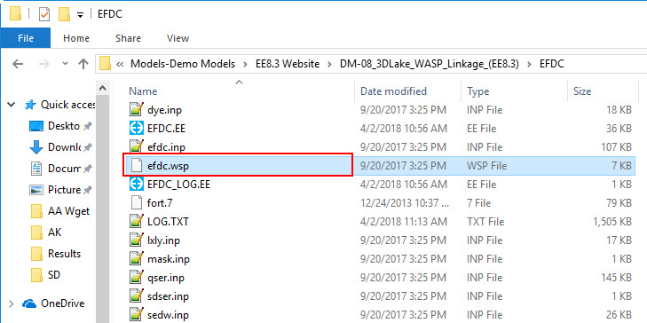
Figure 22 Input files for 3D Lake problem. EFDC.WSP file must be located in folder for EFDC project.
...
When you click on Pre-Processor, this screen is opened. This is the screen where you load the EFDC HYD file. Click the button for ‘Hydrodynamic Linkage File’ and use the browser to locate the EFDC HYD file generated for the project. EFDC writes the HYD file to the EFDC project folder …………….\LakeExample…\DM-08_3DLake_WASP_Linkage_(EE8.3)\EFDC\#output\wasp\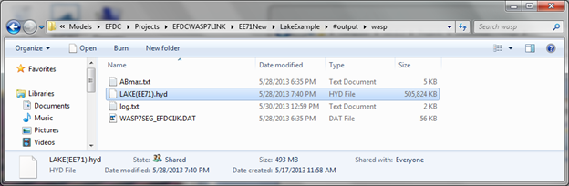
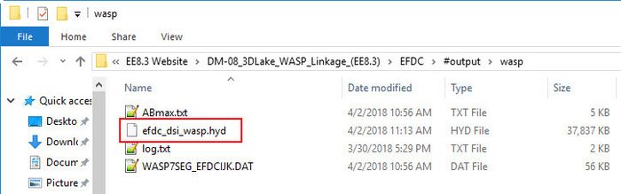
Figure 27 EFDC generated HYD file for 3D Lake problem.
Select and open the HYD file in the WASP7 screen. Path is shown in Figure 23 for the EFDC HYD file for the project.
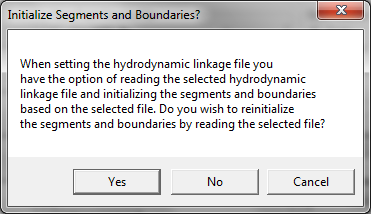
Figure 28- 28 Message from WASP7 when HYD file is selected.
...
Figure 29- EFDC HYD file selected. Click OK to read the HYD file.

Figure 30- 30 Data read from EFDC HYD file for the 3D Lake problem, page 1 of 2
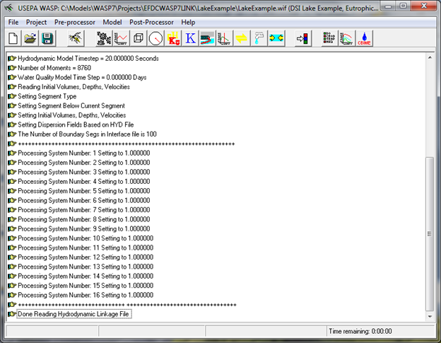
Figure 31- 31 Data read from EFDC HYD file for the 3D Lake problem, page 2 of 2
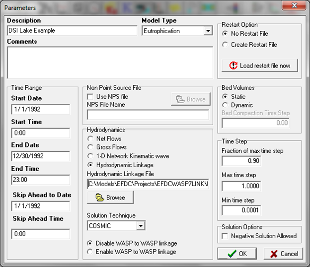
Figure 32- 32 Parameters Screen for Data Set.
...
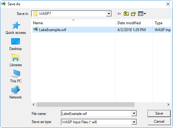
Go back to “File” button on main screen and click ‘Save As’ project file, then you use browser to save the WASP7 project file to the folder for WASP7 projects (not EFDC projects).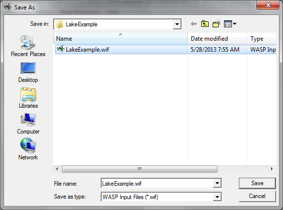
...
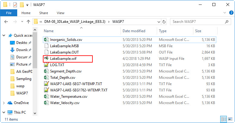
Figure 33- 33 WASP7 project file saved in WASP7 project folder (not the EFDC project folder).
The next set of steps in setting up the WASP7 project is the input of boundary condition data for each state variable and each boundary segment. Screenshots shown in Figure 34 through Figure 43 show the assignment of default boundary condition data and testing the boundary condition settings for the 3D Lake problem.
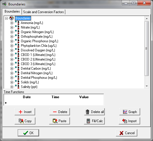
Figure 34- 34 Pre-Processor Selection for (+) Boundaries brings up this screen.
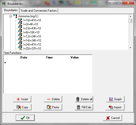
Figure 35- 35 Click on Ammonia (+) and list of boundary segments is displayed.
K=10 is WASP7 surface layer. Boundary data is entered for all 10 vertical layers for each of the boundary locations.
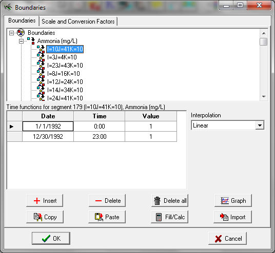
Figure 36- 36 Click on segment I=10 J=41 K=10 and the default setting of 1.0 for boundary condition data is displayed in the Time Function screen.
Ammonia boundary value of 1.0 is set for begin date/time 1/1/1992 00:00 and end date/time 12/30/1992 23:00. WASP7 assigns a default setting of 1.0 for all boundary conditions for all state variables. WASP7 boundary segments are setup with linkage data for the EFDC grid cell model domain. When setting up a new WASP7 project, EPA recommends that a model run be executed at this point to test that the data provided by EFDC hydrodynamic linkage will result in a stable WASP7 model solution. Next step is to go to main screen and execute the WASP7 model to test the boundary settings of 1.0.
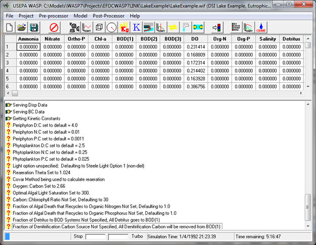
Figure 37- 3 Click on Model and execute WASP7.
Figure 37 shows screen display when WASP7 is executing. Estimate of time remaining for model run is shown at lower right of screen.
Figure 38- 38 WASP7 run has completed successfully.
The linkage of EFDC water temperature with WASP7 water temperature is checked with the WASP7 post-processor. Water temperature is extracted for Wasp7 segment 7 (surface layer) and segment 1762 (bottom layer) (see Figure 39). A lookup table WASP7SEG_EFDCIJK.DAT is written by EFDC to provide a mapping from EFDC (I,J,K) grid cell coordinates to WASP7 segment numbers and vertical layers (see Figure 40). The upper and lower panel shows the mapping of EFDC grid cell L=8 I=4 J=5 for the surface layer (EFDC K=10, WASP7 Layer=1) and the bottom layer (EFDC K=1 WASP7 Layer=10) to WASP7 Segment 7 (surface) and Segment 1792 (bottom).
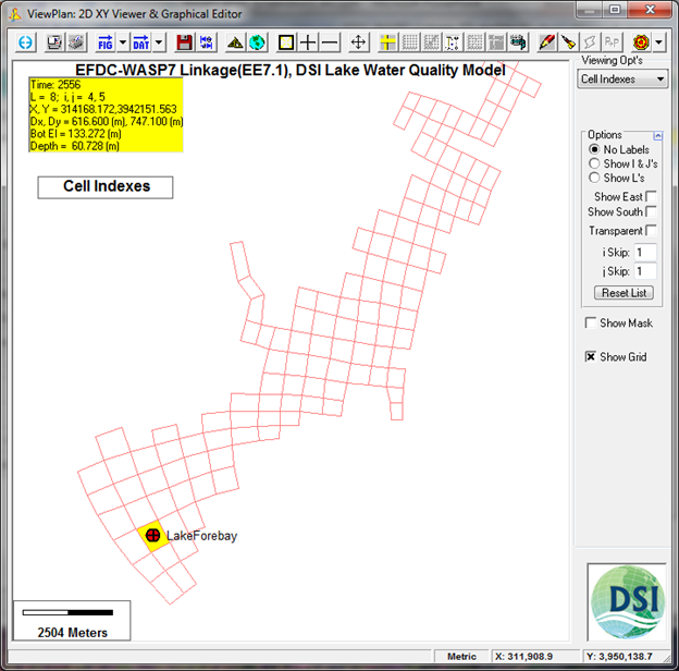
Figure 39-39 EFDC and WASP7 grid cell selected to extract water temperature results.
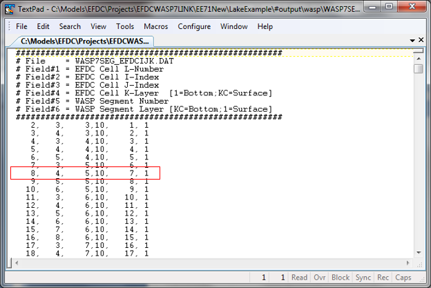
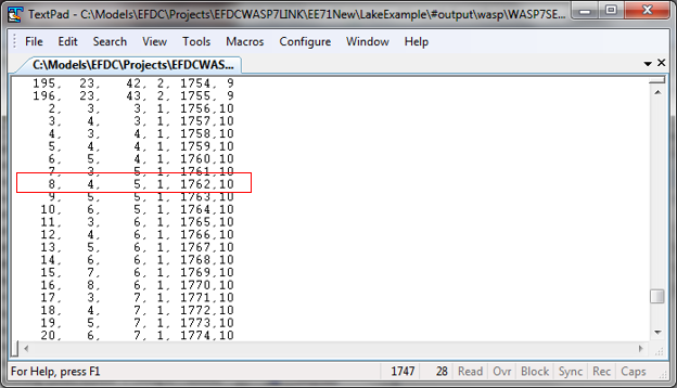
Figure 40-40 WASP7SEG_EFDCIJK.DAT Lookup Table from EFDC (I,J,K) to WASP7 (Segment, Layer)
...
Message pops up; click OK and select the *.BMD file as the output results file for the WASP7 model
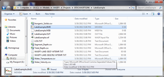
Figure 41- 41 Select BMD file for post-processing time series results
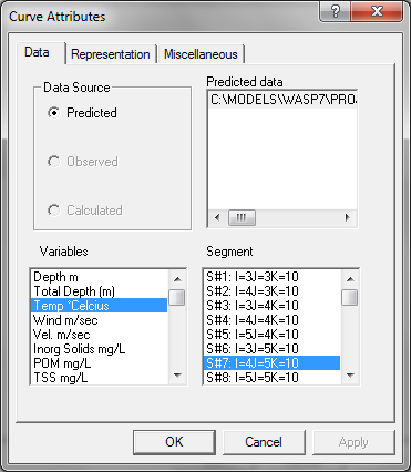
Figure 42-42 Select Water Temperature for viewing in S#7 I=4 J=5 K=10.
This is a surface layer segment near the dam in the forebay shown in the grid cell map (Figure 40).
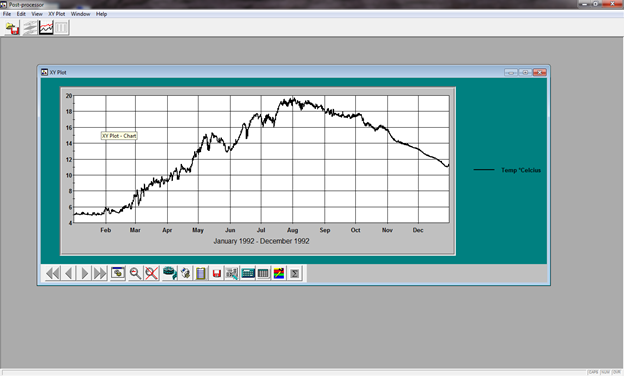
Figure 43-43 Water temperature for Wasp7 segment 7 at forebay, Surface layer.
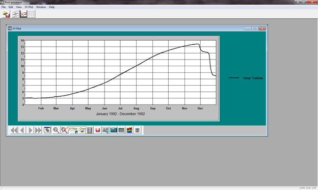
Figure 44-44 Water temperature for Wasp7 segment 1762 at forebay, Bottom layer.
...
Output Control allows the user to write CSV files for selected model output variables. Data is written to CSV files as a flat data block file for all time intervals for all segments. CSV files are selected for a number of model output variables as shown in screenshot below.
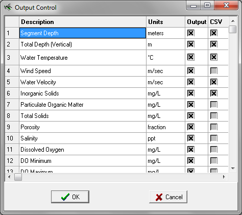
Figure 45- 45 Output Control selection of CSV files for 3D Lake problem
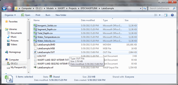
Figure 46- 46 Output CSV files written for 3D Lake problem.
...
Results are extracted from EFDC and WASP7 for surface and bottom layer water temperature for a grid cell in the forebay of the lake (see Figure 39). The time series comparison of model results is shown in Figure 47. As can be seen in the plot, the results match exactly since water temperature is provided to WASP7 in the HYD file linkage.
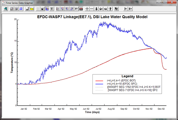
Figure 47- 47 EFDC and WASP7 results for water temperature at grid cell I=4, J=5, K=1 & K=10.
...
The specifications for the computer used for the EFDC and WASP7 model runs for the 3D Lake problem are shown in Figure 48. The run time for a 365 day simulation for the EFDC 3D lake model is given in Error! Reference source not found.Table 1. Total elapsed time for the computer using a single thread was 2.0 hrs. The run time for the lake model with the same computer using 4 threads was 1.1 hrs. The EFDC model simulated hydrodynamics, sediment transport, water quality and sediment diagenesis. The run time for the WASP7 3D lake model, shown in Error! Reference source not found.Table 1, was 5 hrs. The WASP7 model used the linked HYD model for hydrodynamics and simulated sediment and water quality.
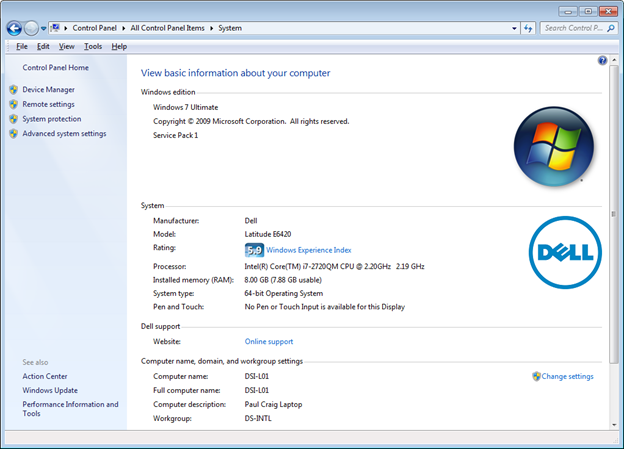
Figure 48-48 Specifications for Windows 7 Computer used for EFDC and WASP7 model runs
...