...
The US Environmental Protection Agency (EPA) supports a number of public domain watershed, hydrodynamic and water quality models for use in water quality management studies including TMDL evaluations. The EPA Watershed & Water Quality Modeling Technical Support Center is the portal for downloading EPA supported models ( http://www.epa.gov/athens/wwqtsc/index.html).
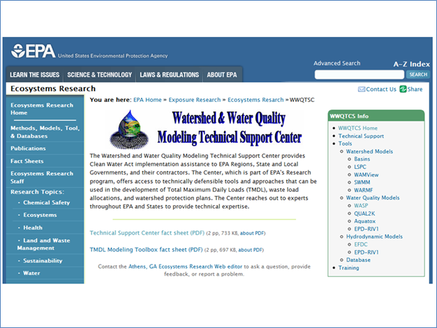
Figure 1- 1 EPA Watershed & Water Quality Modeling Technical Support Center
...
Screenshots of the WASP7 pages from the EPA website are shown below.
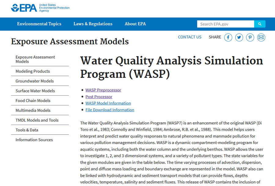
Figure 2- 2 Water Quality Analysis Simulation Program (WASP), page 1 of 2
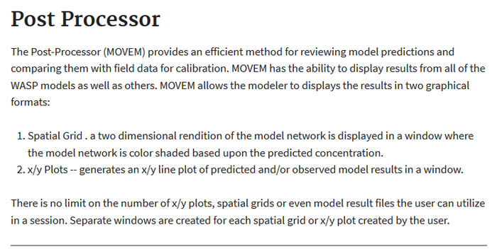
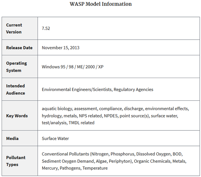
Figure 3- 3 Water Quality Analysis Simulation Program (WASP)
...
The timing of the EFDC model is shown in Figure 15. Linkage with EFDC_Explorer and WASP7 is shown in Figure 16 and Figure 17.
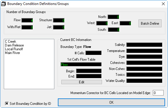
Figure 4- 4 Boundary Conditions for 3D Lake.
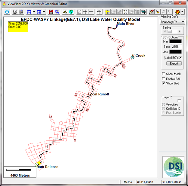
Figure 5- 5 Boundary Condition Locations for 3D Lake. Dashed line shows centerline of lake.
...
Figure 7- Bottom Profile Along Centerline of lake.

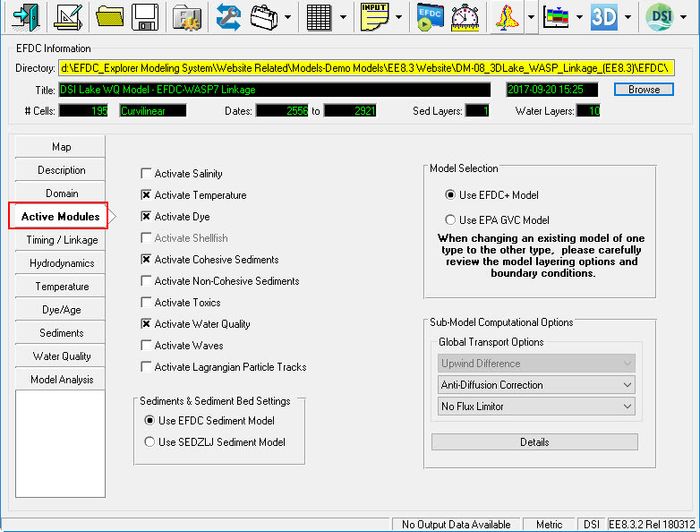
Figure 8- 8 Active Modules for 3D Lake Problem.

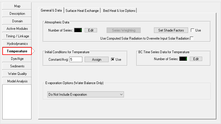
Figure 9- 9 Water Temperature.
Heat/Temperature Option for “Equilibrium Temp (CE-QUAL-W2) Method)” is selected for the 3D lake model.

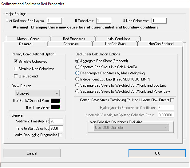
Figure 10-Cohesive Sediment.
One class of cohesive sediment is setup for example problem. One bed layer is required for sediment transport model.
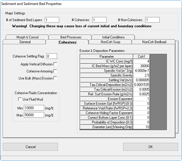
Figure 11- 11 Cohesive Erosion and Deposition Parameters.

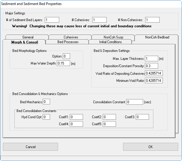
Figure 12- 12 Bed Morphology and Consolidation.

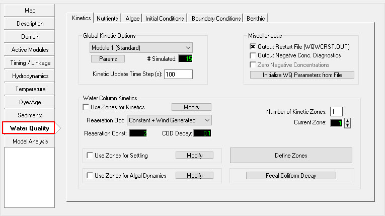
Figure 13- 13 Water Quality. -Module 1 (Standard) is selected.

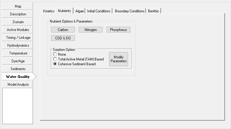
Figure 14- 14 Kinetic coefficients and parameters of the EFDC water quality model.

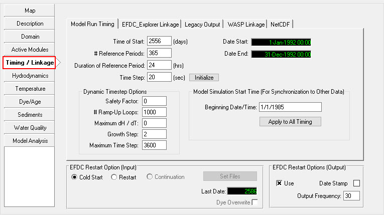
Figure 15- 15 Timing and Linkage for 3D Lake Problem.
1/1/1985 is assigned as the reference base date. The simulation begins on 1 Jan 1992 (day=2556) and ends 365 days later. A time step of 20 seconds is used to maintain a stable solution.

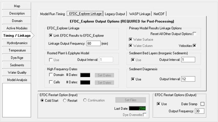
Figure 16- 16 EFDC Explorer Linkage. -EFDC results are written to output files at 60 minute intervals

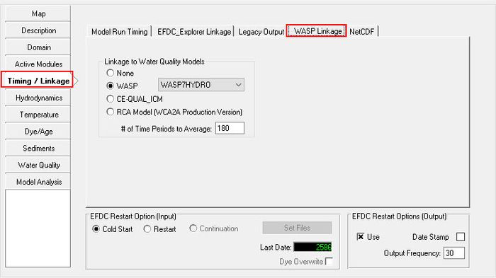
Figure 17- 17 WASP Linkage.
WASP7HYDRO is selected from the drop down list for WASP linkage. The # Time periods to average is assigned 180 to match the 60 minute output interval assigned for EFDC Explorer linkage. With a time step of 20 sec and an EFDC output interval of 60 minutes (=3600 seconds), the EFDC model results are averaged over 180 iterations (180 =3600 sec/20 sec DT).
...
Screenshots of the EFDC.WSP file used for the 3D Lake problem are shown below. The EFDC.WSP text file is included in the files provided for this sample problem. 
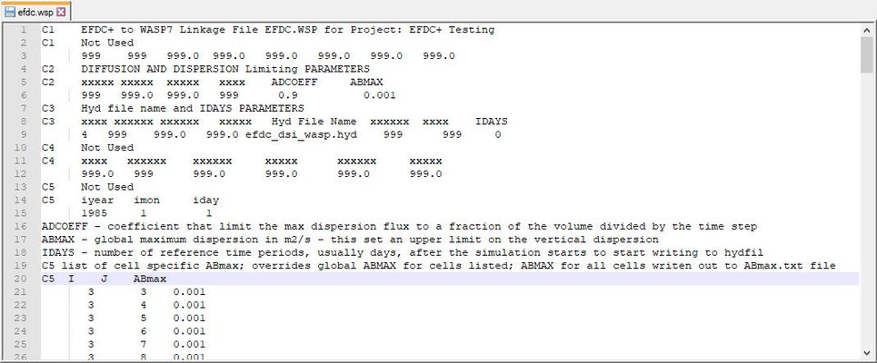
Figure 19- EFDC.WSP Control File used for 3D Lake problem, partial listing.
...
C3 xxxx xxxxxx xxxxxx xxxxx Hyd File Name xxxxxx xxxx IDAYS
4 999 999.0 999.0 LAKE(EE71)efdc_dsi_wasp.hyd 999 999 0
...
1985 1 1
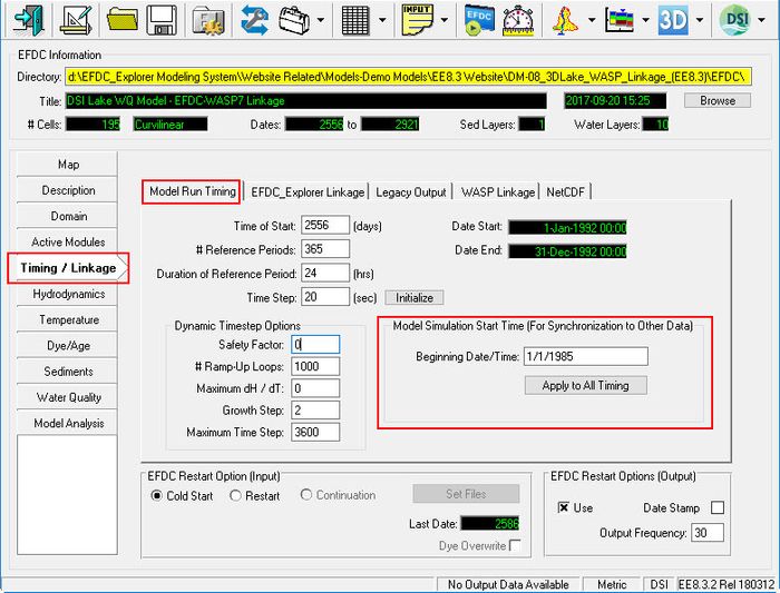
Figure 20- 20 EFDC_Explorer Model Run Timing.
...
First two data columns above provide the sequence of all horizontal (I, J) grid cells that are required for correct setup of the EFDC.WSP control file. The user can prepare a correctly formatted EFDC.WSP file by importing the DXDY.INP file into Excel to get the correct sequence of I and J grid cells. Insert a third column after the imported I, J records from the DXDY.INP and insert the assignment of ABMAX value (as m**2/sec) desired for each grid cell.
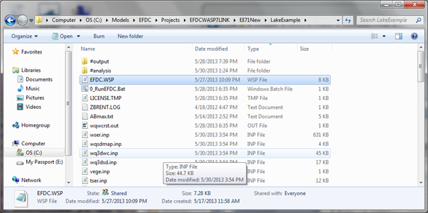
Figure 22--22 Input files for 3D Lake problem. EFDC.WSP file must be located in folder for EFDC project.
...
The user now has the ability to select the model solution technique to be used by the water quality module during the simulation. Currently there are 3 solution techniques that can be selected: 1) Euler – which is the traditional solution technique that has been in WASP since its inception, 2) COSMIC Flux Limiting – this solution technique is typically used when WASP is linked to multi-dimensional hydrodynamic models like EFDC, 3) Runge-Kutta 4 step solution technique used for diurnal simulations.
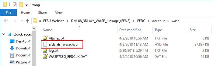
Figure 23- 23 EFDC generated HYD file LAKE(EE71).HYD efdc_dsi_wasp.hyd for 3D Lake problem.
A step-by-step sequence of screen shots is shown in Figure 24 through Figure 33 to illustrate how to link the EFDC generated HYD file to setup and save a new WASP7 project.
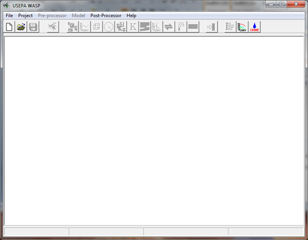
Figure 24- 24 Startup screen when WASP7 is open.
Pre-processor button is grey so data cannot be entered yet. Click on File and select the first item in drop down list to define a ‘New’ file
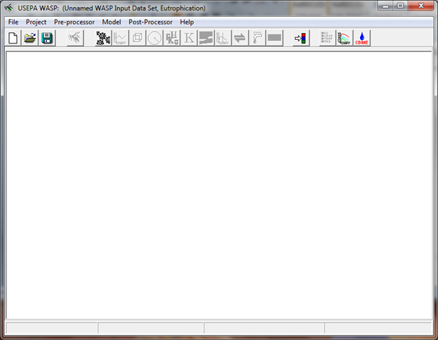
Figure 25- 25 After clicking “New “ the pre-processor button is now ready to be activated to import the EFDC HYD file
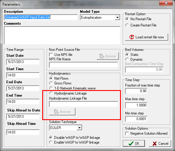
Figure 26- 26 Hydrodynamic Linkage File.
When you click on Pre-Processor, this screen is opened. This is the screen where you load the EFDC HYD file. Click the button for ‘Hydrodynamic Linkage File’ and use the browser to locate the EFDC HYD file generated for the project. EFDC writes the HYD file to the EFDC project folder …………….\LakeExample\#output\wasp\
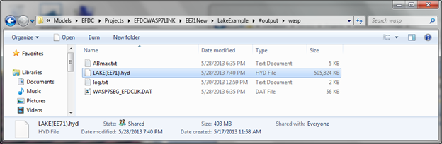
Figure 27- 27 EFDC generated HYD file for 3D Lake problem.
...